Vishay Semiconductor S07B S07D S07G S07J S07M Owner's Manual and User Guide
Summary
These high-voltage, surface-mount small signal diodes are designed for automated placement in modern electronic assemblies while maintaining excellent reliability. Compliant with RoHS and Pb-free standards, they are perfect for engineers designing compact, performance-critical circuits. This comprehensive manual provides essential technical data, including maximum electrical ratings (RRM, DC blocking), detailed thermal characteristics, package dimensions, and suitability for high-temperature soldering processes.
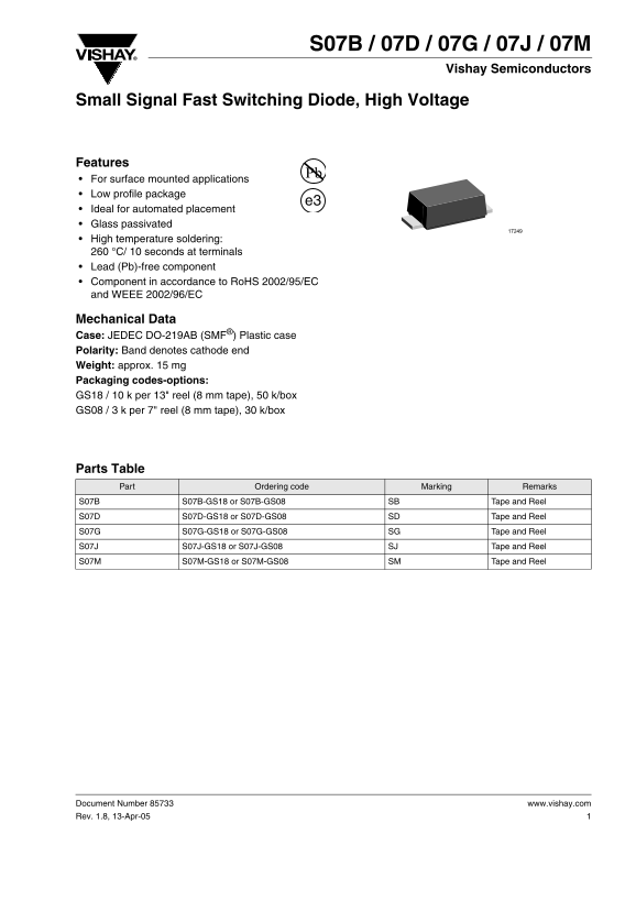
Page 1 Text Content
Vishay Semiconductors
Small Signal Fast Switching Diode, High Voltage
Features For surface mounted applications Low profile package
Ideal for automated placement Glass passivated High temperature soldering: °C/ 10 seconds at terminals Lead (Pb)-free component Component in accordance to Ro HS 2002/95/EC and WEEE 2002/96/EC
Mechanical Data Case: JEDEC DO-219AB (SMF®) Plastic case Polarity: Band denotes cathode end Weight: approx. 15 mg Packaging codes-options: GS18 / 10 k per 13" reel (8 mm tape), 50 k/box GS08 / 3 k per 7" reel (8 mm tape), 30 k/box
Parts Table Part Ordering code Marking Remarks S07B S07B-GS18 or S07B-GS08 SB Tape and Reel S07D S07D-GS18 or S07D-GS08 SD Tape and Reel S07G S07G-GS18 or S07G-GS08 SG Tape and Reel S07J S07J-GS18 or S07J-GS08 SJ Tape and Reel S07M S07M-GS18 or S07M-GS08 SM Tape and Reel
Document Number 85733 www.vishay.com Rev. 1.8, 13-Apr-05
Page Summary Contents For Vishay Semiconductor S07B S07D S07G S07J S07M Owner's Manual and User Guide
Manual Details
| Brand | Vishay |
|---|---|
| Pages | 7 |
| File Size | 117.26 KB |
| Published | June 16, 2026 |
Enter the captcha to get the download link:

Frequently Asked Questions
Are these diodes eco-friendly and compliant with regulations?
Yes, they are Lead (Pb)-free components, meeting both RoHS 2002/95/EC and WEEE 2002/96/EC standards.
What is the suitable maximum temperature for soldering this surface mount device?
The recommended high-temperature soldering process involves 260 °C for a duration of 10 seconds at the terminals.
Which specific model handles the highest reverse voltage rating?
The S07M variant has the highest rated Maximum Repeat Peak Reverse Voltage at 1000 V RRM.
Are these components suitable for medical life-sustaining purposes?
No, the products are expressly stated not to be designed for use in medical, life-saving, or life-sustaining applications.