Toshiba TOSHIBA Photocoupler GaAs Ired & Photo-Transistor TLP628, TLP628-2, TLP628-4 User Manual (1)(1)
Summary
Discover reliable signal isolation with the TLP628 series optocouplers from Toshiba. This technical guide provides comprehensive specifications, including detailed absolute maximum ratings, high isolation voltages (5000Vrms), and operational characteristics for models ranging up to four channels (TLP628-4). Ideal for engineers designing general electronic applications—such as industrial robotics, measuring equipment, or office electronics—seeking dependable signal transmission and circuit protection.
Page 1 Text Content
TLP628,TLP628−2,TLP628−4
TOSHIBA Photocoupler Ga As Ired & Photo−Transistor
TLP628,TLP628−2,TLP628−4 Programmable Controllers Unit in mm DC−Output Module Telecommunication
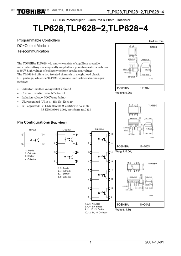
The TOSHIBA TLP628, −2, and −4 consists of a gallium arsenide infrared emitting diode optically coupled to a phototransistor which has a 350V high voltage of collector−emitter breakdown voltage. The TLP628−2 offers two isolated channels in a eight lead plastic DIP package, while the TLP628−4 provide four isolated channels per package.
TOSHIBA 11−5B2
• Collector−emitter voltage: 350 V (min.)
• Current transfer ratio: 50% (min.) Weight: 0.26g
• Isolation voltage: 5000Vrms (min.) • UL recognized: UL1577, file No. E67349 • BSI approved: BS EN60065:2002, certificate no.7426 BS EN60950-1:2002, certificate no.7427
Pin Configurations (top view)
TLP628-2 TLP628-4
TLP628
TOSHIBA 11−10C4
1: Anode
Weight: 0.54g
2: Cathode 3: Emitter 4: Collector
1, 3: Anode 2, 4: Cathode 5, 7: Emitter 6, 8: Collector
1, 3, 5, 7: Anode
TOSHIBA 11−20A3
2, 4, 6, 8: Cathode 9, 11, 13, 15: Emitter Weight: 1.1g 10, 12, 14, 16: Collector
Page Summary Contents For Toshiba TOSHIBA Photocoupler GaAs Ired & Photo-Transistor TLP628, TLP628-2, TLP628-4 User Manual (1)(1)
Manual Details
| Brand | Toshiba |
|---|---|
| Pages | 8 |
| File Size | 263.04 KB |
| Published | May 31, 2026 |
Enter the captcha to get the download link:

Frequently Asked Questions
Which TLP628 model has four isolated channels?
The TLP628−4 provides four isolated channels within the plastic DIP package.
What is the minimum isolation voltage rating for this component?
The absolute minimum stated isolation voltage is 5000Vrms AC for one minute at R.H. ≤ 60%.
Are these components suitable for safety-critical applications like medical instruments?
No, they are not warranted for use in high reliability equipment such as life support or medical instruments ("Unintended Usage").
What precautions should be taken regarding continuous operation under heavy load?
Using the device under continuously heavy loads with significant temperature/current changes may significantly decrease reliability, requiring review of the Semiconductor Reliability Handbook.