Toshiba Photocoupler GaAs Ired & Photo-Transistor TLP141G User Manual
Summary
The TOSHIBA TLP141G mini flat coupler is a highly reliable optocoupler solid-state relay designed for surface mount assembly in high-performance electronics. This technical manual provides comprehensive specifications, including absolute maximum ratings, electrical characteristics, coupling details, and recommended operation guidelines. Ideal for diverse general applications—such as industrial automation, measuring equipment, and consumer electronics—this resource guides engineers through precise product usage and integration best practices.
Page 1 Text Content
TLP141G
TOSHIBA Photocoupler Ga As Ired & Photo−Transistor
TLP141G
Programmable Controllers
Unit in mm
AC−Output Module Solid State Relay
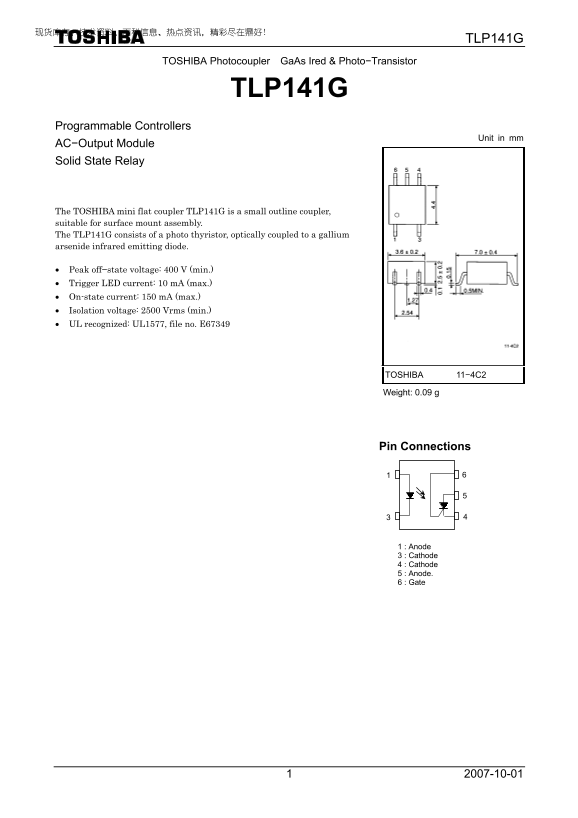
The TOSHIBA mini flat coupler TLP141G is a small outline coupler, suitable for surface mount assembly. The TLP141G consists of a photo thyristor, optically coupled to a gallium arsenide infrared emitting diode.
• Peak off−state voltage: 400 V (min.) • Trigger LED current: 10 m A (max.) • On-state current: 150 m A (max.) • Isolation voltage: 2500 Vrms (min.) • UL recognized: UL1577, file no. E67349
TOSHIBA 11−4C2
Weight: 0.09 g
Pin Connections
1 : Anode 3 : Cathode 4 : Cathode 5 : Anode. 6 : Gate
Page Summary Contents For Toshiba Photocoupler GaAs Ired & Photo-Transistor TLP141G User Manual
Manual Details
| Brand | Toshiba |
|---|---|
| Pages | 6 |
| File Size | 202.56 KB |
| Published | June 06, 2026 |
Enter the captcha to get the download link:

Frequently Asked Questions
What material is used for the infrared emitting diode?
It uses a gallium arsenide (GaAs) infrared emitting diode.
What is the minimum isolation voltage of this coupler?
The specified isolation voltage (BV) is 2500 Vrms.
Does this device have usage limitations regarding high reliability applications?
No, it should not be used in equipment requiring extraordinary quality or intended for 'Unintended Usage,' such as medical instruments or airplane controls.
What are the recommended operating and storage temperature ranges?
The recommended operating range is -25°C to 85°C, while the storage temperature range is -55~125°C.