TI Texas Instruments SLTS139 Data Handbook1/Instructions
Summary
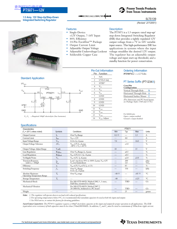
The PT5071 is a high-efficiency, integrated switching regulator designed to provide stable +12V power from variable input voltages ranging from 7V to 16V. This comprehensive datasheet serves as an essential resource for electrical engineers and hardware designers. It covers all technical specifications, including performance graphs, adjustable voltage settings, and detailed application guides necessary for implementing reliable DC-DC power management in complex electronic systems.
Page 1 Text Content
查询PT5071供应商 PT5071—12V 1.5 Amp, 12V Step-Up/Step-Down
SLTS139
Integrated Switching Regulator
(Revised 2/7/2001)
Features Description Single-Device: The PT5071 is a 1.5-ampere rated step-up/ +12V Output, 7-16V Input step-down Integrated Switching Regulator 84% Efficiency (ISR) that provides a tightly regulated 12V 14-Pin Excalibur™ Package output voltage from a 7V to 16V variable Output Current Limit input source. This high-performance ISR has Adjustable Output Voltage applications in systems where the input Adjustable Undervoltage Lockout voltage straddles the desired 12V output. Solderable Copper Case The regulator has an adjustable output
voltage and input start-up threshold, and a standby function for power conservation.
Pin-Out Information Ordering Information Pin Function PT5071¨ = +12 Volts N/C
Standard Application
UVLO Adj
PT Series Suffix (PT1234X)
STBY*
Case/Pin
Configuration
UVadj
IN Vertical Through-Hole
PT5071 Vin Horizontal Through-Hole
IN OUT
GND Horizontal Surface Mount
GND 0adj STBY*
7-10 GND
(For dimensions and PC board layout, see Package Styles 1360 and 1370.)
GND GND Vout Vout
For Inhibit pin:
C1, C2 = Required 100µF electrolytic (See footnotes) Open = output enabled
Vout Adjust Ground = output disabled
Specifications
Characteristics PT5071
(Ta = 25°C unless noted) Symbols Conditions Min Typ Max Units Output Current Io Over Vin Range 0.1 (1) 1.5 Current Limit Ilim Vin = 12V 4.0 Input Voltage Range Vin 0.1A ≤ Io ≤ Iomax 7.0 16.0 Output Voltage Tolerance ∆Vo Vin =12V, Io =Iomax ±1.0
–40°C ≤ Ta ≤ +85°C
Output Voltage Adjust Range Voadj Line Regulation Regline Over Vin Range, Io =Iomax ±0.5 Load Regulation Regload Vin =12V, 0.1 ≤ Io ≤ Iomax ±0.5 Vo Ripple/Noise Vn Vin =12V, Io =Iomax ±2.0 ±3.0
Transient Response ttr Load step from 50% to 100% Iomax, Vin=12V µSec
with C2 = 100µF Vos Vo over/undershoot 1.0 %Vo Efficiency Vin =12V, Vo=12V, Io =1.5A
Switching Frequency ƒo Over Vin Range k Hz 0.1A ≤ Io ≤ Iomax Absolute Maximum Ta Over Vin range –40 (2) +85 (3) °C
Operating Temperature Range Storage Temperature Ts –40 +125 °C Mechanical Shock Per Mil-STD-883D, Method 2002.3 , 1 msec, TBD G’s
Half Sine, mounted to a fixture
Mechanical Vibration Per Mil-STD-883D, Method 2007.2,
20-2000 Hz, Soldered in a PC board TBD G’s
Weight grams Notes: 1. The regulator will operate down to no load with reduced specifications. 2. For operating temperatures below 0°C, it is recommended that tantalum capacitors be used at both the input and output. 3. See SOA curves, or contact the factory for derating guidelines. Input/Output Capacitors: The PT5071 regulator requires a 100µF electrolytic capacitor at the input and output for proper operation in all applications. The ESR (equivalent series resistance) of both capacitors must be less than 250mΩ @100k Hz. In addition, C1 and C2 must be rated to a minimum of 300m Arms ripple current.
For technical support and more information, see inside back cover or visit www.ti.com/powertrends
Page Summary Contents For TI Texas Instruments SLTS139 Data Handbook1/Instructions
Manual Details
| Brand | Texas Instruments |
|---|---|
| Pages | 4 |
| File Size | 131.46 KB |
| Published | June 02, 2026 |
Enter the captcha to get the download link:

Frequently Asked Questions
What is the maximum current and voltage range of this regulator?
The PT5071 handles a regulated +12V output up to 1.5 Amps, accepting an input voltage between 7V and 16V.
Are there specific components needed for correct operation?
Yes, the device requires a 100μF electrolytic capacitor at both the input and output. Both capacitors must have an ESR less than 250mW @100kHz.
Does it offer adjustable voltage or power saving features?
It includes circuitry for adjustable output voltage (ranging from 10V to 15V) and features a STBY pin to allow for standby power conservation.