Texas Instruments - SN54273, SN54LS273, SN74273, SN74LS273 Octal D-Type Flip-Flop with Clear Data Sheet Manual
Summary
A reliable octal D-Type Flip-Flop with Clear is a core component for digital circuit design, providing robust memory storage and data shifting capabilities using TTL logic. This manual serves as a comprehensive technical guide, detailing key functionality, electrical specifications (voltage levels, timing diagrams), operational parameters, and application guidelines. It is an essential resource for electronics engineers and hardware designers constructing synchronous, positive-edge-triggered circuits requiring precise digital control.
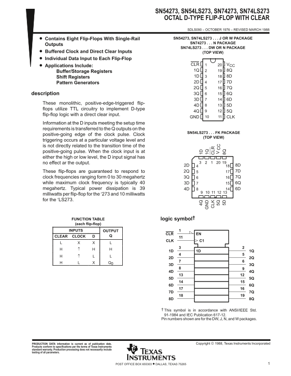
Page 1 Text Content
SN54273, SN54LS273, SN74273, SN74LS273 OCTAL D-TYPE FLIP-FLOP WITH CLEAR
SDLS090 – OCTOBER 1976 – REVISED MARCH 1988
Contains Eight Flip-Flops With Single-Rail SN54273, SN74LS273 J OR W PACKAGE
SN74273 N PACKAGE
Outputs
SN74LS273 DW OR N PACKAGE
Buffered Clock and Direct Clear Inputs (TOP VIEW) Individual Data Input to Each Flip-Flop
CLR VCC
Applications Include:
Buffer/Storage Registers 1Q 8Q Shift Registers 1D 8D Pattern Generators 2D 7D 2Q 7Q description 3Q 6Q 3D 6D
These monolithic, positive-edge-triggered flip-
flops utilize TTL circuitry to implement D-type
flip-flop logic with a direct clear input.
GND CLK
Information at the D inputs meeting the setup time requirements is transferred to the Q outputs on the
SN54LS273 FK PACKAGE
positive-going edge of the clock pulse. Clock
(TOP VIEW)
triggering occurs at a particular voltage level and is not directly related to the transition time of the positive-going pulse. When the clock input is at either the high or low level, the D input signal has no effect ar the output.
2D 8D These flip-flops are guaranteed to respond to 2Q 7D clock frequencies ranging form 0 to 30 megahertz 3Q 7Q
while maximum clock frequency is typically 40 3D 6Q megahertz. Typical power dissipation is 39 4D 6D milliwatts per flip-flop for the ′273 and 10 milliwatts for the ′LS273. 4Q 1D
LK LR logic symbol† 5Q
FUNCTION TABLE (each flip-flop) 5D 8Q INPUTS OUTPUT
CLR EN
CLEAR CLOCK
CLK C1
This symbol is in accordance with ANSI/IEEE Std. 91-1984 and IEC Publication 617-12. Pin numbers shown are for the DW, J, N, and W packages.
PRODUCTION DATA information is current as of publication date. Copyright 1988, Texas Instruments Incorporated
Products conform to specifications per the terms of Texas Instruments standard warranty. Production processing does not necessarily include testing of all parameters.
1POST OFFICE BOX 655303 • DALLAS, TEXAS 75265
Page Summary Contents For Texas Instruments - SN54273, SN54LS273, SN74273, SN74LS273 Octal D-Type Flip-Flop with Clear Data Sheet Manual
Manual Details
| Brand | Texas Instruments |
|---|---|
| Pages | 6 |
| File Size | 95.87 KB |
| Published | June 04, 2026 |
Enter the captcha to get the download link:

Frequently Asked Questions
What is the typical operating temperature range for the SN54273?
The recommended operating temperature range is -55°C to 125°C.
How does the output voltage behave when the clock input is high or low?
When the clock input is at either the high or low level, the D input signal has no effect on the output.
What is the maximum guaranteed frequency range for these flip-flops?
They are guaranteed to respond to clock frequencies from 0 to 30 megahertz.
What is the standard power dissipation per flip-flop for SN54LS273?
The typical power dissipation for 'LS273 is stated as 10 milliwatts per flip-flop.