ST M74HCT74 Dual D-Type Flip-Flop with Preset and Clear Data Sheet
Summary
This is a high-speed CMOS Dual D Type Flip Flop with clear functionality, designed for robust digital signal processing applications. The comprehensive manual provides detailed technical specifications essential for system integration, covering electrical characteristics, timing diagrams (setup/hold times), and operational limits across various temperature ranges. It ensures compatibility and reliable performance in complex digital circuits requiring stable data handling. Ideal for electronics engineers, hardware developers, and embedded systems designers building high-frequency logic using TTL or CMOS interfaces.
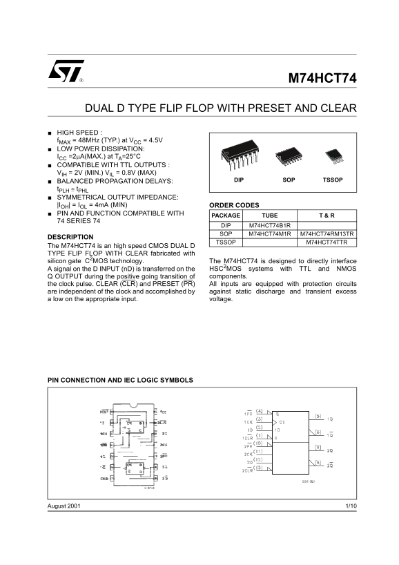
Page 1 Text Content
M74HCT74
DUAL D TYPE FLIP FLOP WITH PRESET AND CLEAR
HIGH SPEED : f MAX = 48MHz (TYP.) at VCC = 4.5V LOW POWER DISSIPATION: ICC =2µA(MAX.) at TA=25°C COMPATIBLE WITH TTL OUTPUTS : VIH = 2V (MIN.) VIL = 0.8V (MAX)
BALANCED PROPAGATION DELAYS: SOP TSSOPDIP
t PLH ≅ t PHL SYMMETRICAL OUTPUT IMPEDANCE: |IOH| = IOL = 4m A (MIN) ORDER CODES PIN AND FUNCTION COMPATIBLE WITH
PACKAGE TUBE T & R
74 SERIES 74
DIP M74HCT74B1R SOP M74HCT74M1R M74HCT74RM13TR
DESCRIPTION
TSSOP M74HCT74TTR
The M74HCT74 is an high speed CMOS DUAL D TYPE FLIP FLOP WITH CLEAR fabricated with silicon gate C2MOS technology. The M74HCT74 is designed to directly interface
A signal on the D INPUT (n D) is transferred on the HSC2MOS systems with TTL and NMOS Q OUTPUT during the positive going transition of components. the clock pulse. CLEAR (CLR) and PRESET (PR) All inputs are equipped with protection circuits are independent of the clock and accomplished by against static discharge and transient excess a low on the appropriate input. voltage.
PIN CONNECTION AND IEC LOGIC SYMBOLS
1/10August 2001
Page Summary Contents For ST M74HCT74 Dual D-Type Flip-Flop with Preset and Clear Data Sheet
Manual Details
| Brand | CLEAR |
|---|---|
| Pages | 10 |
| File Size | 436.26 KB |
| Published | May 18, 2026 |
Enter the captcha to get the download link:

Frequently Asked Questions
What are the recommended operating voltage ranges?
The recommended supply voltage (VCC) range is 4.5 to 5.5 V.
How do I initialize the flip-flop using asynchronous inputs?
Use CLEAR (CLR) for reset and PRESET (PR) for set functionality asynchronous to the clock.
What are the timing requirements for proper operation?
The setup time ($t_{su}$) must be greater than 7 ns, and the hold time ($t_{h}$) must be 0 ns at standard operating temperatures.