Texas Instruments CD54 CD74HCT147 High-Speed CMOS Logic 10-to-4 Line Priority Encoder User Manual
Summary
A robust 10-to-4 Line Priority Encoder solution, this guide details the high-speed CMOS logic functions of the CD54HC147 and CD74HCT147 series. These devices accept signals from nine inputs and reliably provide a binary representation on four outputs. The technical manual provides comprehensive coverage of electrical compatibility (TTL/CMOS), operational specifications, thermal performance (-55°C to 125°C), and low-power advantages. This component is primarily intended for hardware engineers and electronic designers building systems requiring reliable, high-speed input decoding and signal prioritization within demanding temperature ranges.
Page 1 Text Content
CD54/74HC147, CD74HCT147
Data sheet acquired from Harris Semiconductor SCHS149A
High Speed CMOS Logic
September 1997 - Revised May 2000 10-to-4 Line Priority Encoder
Features The ’HC147 and CD74HCT147 9-input priority encoders [ /Title accept data from nine active LOW inputs (l1 to l9) and
Buffered Inputs and Outputs provide binary representation on the four active LOW inputs
(CD74
(Y0 to Y3). priority is assigned to each input so that when
Typical Propagation Delay: 13ns at VCC = 5V,
HC147
two or more inputs are simultaneously active, the input with
CL = 15p F, TA = 25o C
the highest priority is represented on the output, with input
Fanout (Over Temperature Range) line l9 having the highest priority.
Standard Outputs . . . . . . . . . . . . . . . 10 LSTTL Loads
HCT14 These devices provide the 10-line to 4-line priority encoding
Bus Driver Outputs . . . . . . . . . . . . . 15 LSTTL Loads
7) function by use of the implied decimal “zero”. The “zero” is encoded when all nine data inputs are HIGH, forcing all four
/Sub- Wide Operating Temperature Range . . . -55o C to 125o C
outputs HIGH.
ject Balanced Propagation Delay and Transition Times (High Ordering Information
Significant Power Reduction Compared to LSTTL
Speed Logic ICs
TEMP. RANGE
HC Types PART NUMBER (o C) PACKAGE
Logic
2V to 6V Operation
CD54HC147F3A -55 to 125 16 Ld CERDIP
10-to-4 High Noise Immunity: NIL = 30%, NIH = 30% of VCC
Line at VCC = 5V CD74HC147E -55 to 125 16 Ld PDIP
Prior- HCT Types
CD74HC147M -55 to 125 16 Ld SOIC
ity 4.5V to 5.5V Operation
CD74HCT147E -55 to 125 16 Ld PDIP
Encode Direct LSTTL Input Logic Compatibility,
VIL= 0.8V (Max), VIH = 2V (Min) CD74HCT147M -55 to 125 16 Ld SOIC
CMOS Input Compatibility, Il 1µA at VOL, VOH
/Autho NOTES:
r () 1. When ordering, use the entire part number. Add the suffix to
Description
obtain the variant in the tape and reel.
/Key-
2. Wafer or die for this part number is available which meets all elec-
The ’HC147 and CD74HCT147 are high speed silicon-gate
words
trical specifications. Please contact your local TI sales office or
CMOS devices and are pin-compatible with low power
(High customer service for ordering information.
Schottky TTL (LSTTL).
Speed CMOS
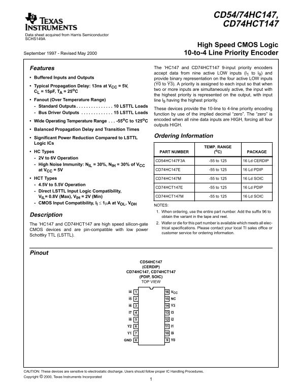
Logic Pinout
10-to-4
CD54HC147 Line (CERDIP) CD74HC147, CD74HCT147
Prior-
(PDIP, SOIC)
ity TOP VIEW Encode
I4 VCC
r, High
I5 NC
Speed
Logic
10-to-4
Prior-
GND Y0
CAUTION: These devices are sensitive to electrostatic discharge. Users should follow proper IC Handling Procedures. Copyright © 2000, Texas Instruments Incorporated
Page Summary Contents For Texas Instruments CD54 CD74HCT147 High-Speed CMOS Logic 10-to-4 Line Priority Encoder User Manual
Manual Details
| Brand | Texas Instruments |
|---|---|
| Pages | 6 |
| File Size | 33.32 KB |
| Published | May 28, 2026 |
Enter the captcha to get the download link:
