Texas Instruments CD54/74HC4040, CD54/74HCT4040 High-Speed CMOS Logic 12-Stage Binary Counter Owner's Manual
Summary
Discover the CD54/74HC4040 series, a robust 12-stage ripple-carry binary counter IC designed for high-speed CMOS logic applications. This fully static counter features buffered inputs and outputs, ensuring reliable performance across extreme temperatures (-55°C to 125°C). The accompanying manual is an essential technical resource for electronics engineers and designers, providing complete details on electrical specifications, functional diagrams, timing parameters, and various physical packages (PDIP/SOIC), allowing for precise integration of counting functionality into demanding digital circuits.
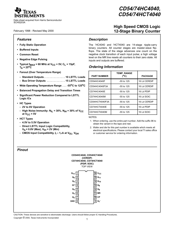
Page 1 Text Content
CD54/74HC4040, CD54/74HCT4040
Data sheet acquired from Harris Semiconductor SCHS203A
High Speed CMOS Logic
February 1998 - Revised May 2000 12-Stage Binary Counter
Features Description Fully Static Operation The ’HC4040 and ’HCT4040 are 14-stage ripple-carry
binary counters. All counter stages are master-slave flip-
[ /Title Buffered Inputs
flops. The state of the stage advances one count on the (CD74H Common Reset negative clock transition of each input pulse; high voltage level on the MR line resets all counters to their zero state. All
Negative Edge Pulsing
inputs and outputs are buffered.
CD74HC
Typical f MAX = 60 MHz at VCC = 5V, CL = 15p F,
T4040) Ordering Information
TA = 25o C
/Subject
Fanout (Over Temperature Range)
TEMP. RANGE
(High
PART NUMBER (o C) PACKAGE
Standard Outputs . . . . . . . . . . . . . . . 10 LSTTL Loads
Speed
Bus Driver Outputs . . . . . . . . . . . . . 15 LSTTL Loads CD54HC4040F -55 to 125 16 Ld CERDIP
Logic Wide Operating Temperature Range . . . -55o C to 125o C
CD54HC4040F3A -55 to 125 16 Ld CERDIP
12-Stage Balanced Propagation Delay and Transition Times
CD74HC4040E -55 to 125 16 Ld PDIP
Binary
Significant Power Reduction Compared to LSTTL
CD74HC4040M -55 to 125 16 Ld SOIC
Logic ICs
CD54HCT4040F3A -55 to 125 16 Ld CERDIP
HC Types
2V to 6V Operation CD74HCT4040E -55 to 125 16 Ld PDIP
High Noise Immunity: NIL = 30%, NIH = 30% of VCC
CD74HCT4040M -55 to 125 16 Ld SOIC
at VCC = 5V
NOTES:
HCT Types
1. When ordering, use the entire part number. Add the suffix to
4.5V to 5.5V Operation
obtain the variant in the tape and reel.
Direct LSTTL Input Logic Compatibility,
2. Wafer and die for this part number is available which meets all
VIL= 0.8V (Max), VIH = 2V (Min)
electrical specifications. Please contact your local TI sales office
CMOS Input Compatibility, Il 1µA at VOL, VOH or customer service for ordering information.
Pinout
CD54HC4040, CD54HCT4040
(CERDIP)
CD74HC4040, CD74HCT4040 (PDIP, SOIC)
TOP VIEW
Q12 VCC Q6 Q11 Q5 Q10
Q3 MR Q2 CP GND Q1‘
CAUTION: These devices are sensitive to electrostatic discharge. Users should follow proper IC Handling Procedures. Copyright © 2000, Texas Instruments Incorporated
Page Summary Contents For Texas Instruments CD54/74HC4040, CD54/74HCT4040 High-Speed CMOS Logic 12-Stage Binary Counter Owner's Manual
Manual Details
| Brand | Texas Instruments |
|---|---|
| Pages | 9 |
| File Size | 52.96 KB |
| Published | May 28, 2026 |
Enter the captcha to get the download link:

Frequently Asked Questions
What is the operating temperature range for these devices?
The temperature range is specified as -55°C to 125°C.
Are there different options based on supply voltage?
Yes. HC types operate from 2V to 6V, while HCT types are designed for 4.5V to 5.5V.
What safety measures should users take when handling the ICs?
Users must follow proper IC Handling Procedures because these devices are sensitive to electrostatic discharge.