ST TSM111 Triple Voltage and Current Supervisor Data Handbook
Summary
The TSM111 is an advanced triple voltage and current supervisor IC designed for robust power management in SMPS applications. This chip provides essential overvoltage and overcurrent protection across critical rails (3.3V, 5V, 12V) without needing external components. The manual offers comprehensive technical details on its functionality, including Power Good circuitry, programmable timing delays, and remote control capability for superior system monitoring. It is the ideal solution for electrical engineers developing reliable computer power systems that require precise supervision across a wide supply voltage range (14.5V to 36V).
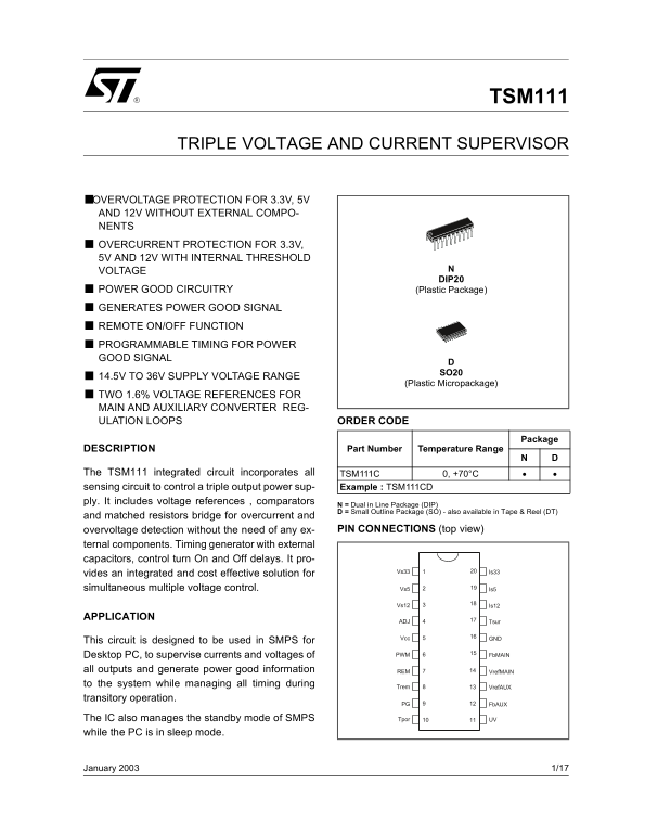
Page 1 Text Content
TSM111
TRIPLE VOLTAGE AND CURRENT SUPERVISOR
■OVERVOLTAGE PROTECTION FOR 3.3V, 5V AND 12V WITHOUT EXTERNAL COMPO- NENTS OVERCURRENT PROTECTION FOR 3.3V, 5V AND 12V WITH INTERNAL THRESHOLD VOLTAGE
DIP20
POWER GOOD CIRCUITRY (Plastic Package)
GENERATES POWER GOOD SIGNAL REMOTE ON/OFF FUNCTION PROGRAMMABLE TIMING FOR POWER GOOD SIGNAL
14.5V TO 36V SUPPLY VOLTAGE RANGE
(Plastic Micropackage)
TWO 1.6% VOLTAGE REFERENCES FOR MAIN AND AUXILIARY CONVERTER REG- ULATION LOOPS ORDER CODE
Package
DESCRIPTION Part Number Temperature Range
The TSM111 integrated circuit incorporates all TSM111C 0, +70°C
sensing circuit to control a triple output power sup- Example : TSM111CD
ply. It includes voltage references , comparators
N = Dual in Line Package (DIP) D = Small Outline Package (SO) - also available in Tape & Reel (DT)
and matched resistors bridge for overcurrent and
overvoltage detection without the need of any ex- PIN CONNECTIONS (top view)
ternal components. Timing generator with external capacitors, control turn On and Off delays. It pro-
20Vs33 Is33
vides an integrated and cost effective solution for simultaneous multiple voltage control. Vs5 Is5
Vs12 Is12
APPLICATION
ADJ Tsur
Vcc GND
This circuit is designed to be used in SMPS for
Desktop PC, to supervise currents and voltages of PWM Fb MAIN
all outputs and generate power good information REM Vref MAIN
to the system while managing all timing during Trem
Vref AUX
transitory operation.
PG Fb AUX
The IC also manages the standby mode of SMPS Tpor UV
while the PC is in sleep mode.
January 2003 1/17
Page Summary Contents For ST TSM111 Triple Voltage and Current Supervisor Data Handbook
Manual Details
| Brand | Current |
|---|---|
| Pages | 17 |
| File Size | 793.66 KB |
| Published | May 18, 2026 |
Enter the captcha to get the download link:

Frequently Asked Questions
What is the maximum supply voltage for the TSM111?
The operating range for the DC Supply Voltage (Vcc) is 15 V to 36 V.
How does the TSM111 provide overvoltage protection?
It incorporates sensing circuits to detect overvoltage on the 3.3V, 5V, and 12V outputs without external components.
What are the minimum requirements for the DC supply voltage (Vcc)?
The Vcc must be higher than the maximum applied voltage of all lines plus an additional 2V (e.g., if Is12 is 13.2V, Vcc needs to be at least 15.2V).
Can I adjust the power good signal timing?
Yes, the IC features programmable timing for the Power Good signal using external capacitors and resistors.
What is the primary function of this chip in a desktop PC?
It sends power good information to the system while supervising the currents and voltages of all outputs (3.3V, 5V, and 12V).