LINEAR TECHNOLOGY LT1769 1769fa Constant-Current Constant-Voltage 2A Battery Charger with Input Current Limiting
Summary
The LT1769 is a sophisticated constant-current/constant-voltage PWM battery charger built for reliable power management systems. It provides an efficient solution to charge various rechargeable batteries, including Li-Ion, NiMH, and NiCd, up to 2A with extremely high precision. Featuring programmable current limiting, automatic safety mechanisms, and voltage sensing, this component is essential for engineers designing advanced energy storage circuits and professional equipment requiring superior charging control.
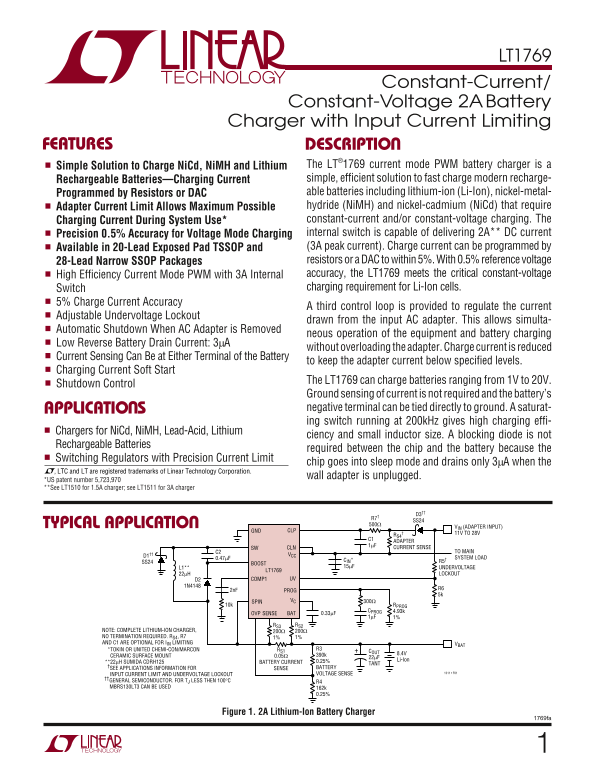
Page 1 Text Content
LT1769
Constant-Current/
Constant-Voltage 2A Battery Charger with Input Current Limiting
FEATURES DESCRIPTIO
Simple Solution to Charge Ni Cd, Ni MH and Lithium The LT®1769 current mode PWM battery charger is a Rechargeable Batteries—Charging Current simple, efficient solution to fast charge modern recharge- Programmed by Resistors or DAC able batteries including lithium-ion (Li-Ion), nickel-metal- Adapter Current Limit Allows Maximum Possible hydride (Ni MH) and nickel-cadmium (Ni Cd) that require Charging Current During System Use* constant-current and/or constant-voltage charging. The Precision 0.5% Accuracy for Voltage Mode Charging internal switch is capable of delivering 2A** DC current Available in 20-Lead Exposed Pad TSSOP and (3A peak current). Charge current can be programmed by 28-Lead Narrow SSOP Packages resistors or a DAC to within 5%. With 0.5% reference voltage High Efficiency Current Mode PWM with 3A Internal accuracy, the LT1769 meets the critical constant-voltage Switch charging requirement for Li-Ion cells.
5% Charge Current Accuracy
A third control loop is provided to regulate the current
Adjustable Undervoltage Lockout
drawn from the input AC adapter. This allows simulta-
Automatic Shutdown When AC Adapter is Removed
neous operation of the equipment and battery charging
Low Reverse Battery Drain Current: 3µA
without overloading the adapter. Charge current is reduced
Current Sensing Can Be at Either Terminal of the Battery
to keep the adapter current below specified levels.
Charging Current Soft Start
The LT1769 can charge batteries ranging from 1V to 20V.
Shutdown Control
Ground sensing of current is not required and the battery’s APPLICATIO S negative terminal can be tied directly to ground. A saturat- ing switch running at 200k Hz gives high charging effi-
Chargers for Ni Cd, Ni MH, Lead-Acid, Lithium
ciency and small inductor size. A blocking diode is not
Rechargeable Batteries
required between the chip and the battery because the
Switching Regulators with Precision Current Limit
chip goes into sleep mode and drains only 3µA when the
, LTC and LT are registered trademarks of Linear Technology Corporation.
wall adapter is unplugged.
*US patent number 5,723,970 **See LT1510 for 1.5A charger; see LT1511 for 3A charger
TYPICAL APPLICATIO 500Ω
VIN (ADAPTER INPUT)
GND CLP
RS4 11V TO 28V
C1 ADAPTER 1µF CURRENT SENSE
SW CLN
C2 TO MAIN
D1†† VCC
0.47µF SYSTEM LOAD
SS24 CIN* R5†
BOOST
L1** 15µF UNDERVOLTAGE
LT1769
22µH LOCKOUT
D2 COMP1 UV
SPIN VC 300Ω
10k RPROG
CPROG 4.93k
OVP SENSE BAT 0.33µF
RS3 RS2
NOTE: COMPLETE LITHIUM-ION CHARGER, 200Ω 200Ω NO TERMINATION REQUIRED. RS4, R7 1% 1% AND C1 ARE OPTIONAL FOR IIN LIMITING VBAT
*TOKIN OR UNITED CHEMI-CON/MARCON RS1 R3
CERAMIC SURFACE MOUNT 0.05Ω 22µF
0.25% Li-Ion
**22µH SUMIDA CDRH125 BATTERY CURRENT TANT
†SEE APPLICATIONS INFORMATION FOR SENSE BATTERY
VOLTAGE SENSE 1511 • F01
INPUT CURRENT LIMIT AND UNDERVOLTAGE LOCKOUT ††GENERAL SEMICONDUCTOR. FOR TJ LESS THEN 100°C
MBRS130LT3 CAN BE USED 162k
Figure 1. 2A Lithium-Ion Battery Charger
1769fa
Page Summary Contents For LINEAR TECHNOLOGY LT1769 1769fa Constant-Current Constant-Voltage 2A Battery Charger with Input Current Limiting
Manual Details
| Brand | Current |
|---|---|
| Pages | 16 |
| File Size | 231.64 KB |
| Published | May 18, 2026 |
Enter the captcha to get the download link:

Frequently Asked Questions
What types of batteries can the LT1769 charge?
It can charge NiCd, NiMH, and Lithium batteries, including Li-Ion.
How is the charging current determined?
The current can be programmed by resistors or a DAC to within 5%.
What are the operational voltage limits for charging?
The charger can operate on batteries ranging from 1V to 20V. I (Average) draw is up to 2A.
Does the charger automatically shut down if power is lost?
Yes, it has an automatic shutdown feature and low reverse battery drain current (3mA).
What must be done when using the 20-Lead TSSOP package?
The exposed pad must be soldered to the PCB ground plane for proper heat sinking.