LINEAR TECHNOLOGY LTC1622 Low Input Voltage Current Mode Step-Down DC DC Controller Data Sheet User Manual
Summary
The LTC1622 is a highly efficient constant frequency DC/DC controller designed for low input voltage applications (2V to 10V). This manual provides comprehensive technical specifications detailing its core features, including high efficiency, excellent line and load regulation, and advanced operational modes like Burst Mode and Shutdown. It enables designers of battery-powered equipment, portable computers, and cellular devices to create energy-optimized power systems by allowing for low quiescent current draw and configurable synchronization frequencies up to 750kHz.
Page 1 Text Content
LTC1622
Low Input Voltage Current Mode Step-Down DC/DC Controller
FEATURES DESCRIPTIO High Efficiency The LTC®1622 is a constant frequency current mode step- Constant Frequency 550k Hz Operation down DC/DC controller providing excellent AC and DC load VIN Range: 2V to 10V and line regulation. The device incorporates an accurate
Multiampere Output Currents undervoltage feature that shuts the LTC1622 down when OPTI-LOOPTM Compensation Minimizes COUT the input voltage falls below 2V.
Selectable, Burst Mode Operation
The LTC1622 boasts a ±1.9% output voltage accuracy and
Low Dropout Operation: 100% Duty Cycle
consumes only 350µA of quiescent current. For applica-
Synchronizable up to 750k Hz
tions where efficiency is a prime consideration and the
Current Mode Operation for Excellent Line and Load
load current varies from light to heavy, the LTC1622 can
Transient Response
be configured for Burst Mode TM operation. Burst Mode
Low Quiescent Current: 350µA
operation enhances low current efficiency and extends
Shutdown Mode Draws Only 15µA Supply Current
battery run time. Burst Mode operation is inhibited during
±1.9% Reference Accuracy
synchronization or when the SYNC/MODE pin is pulled low
Available in 8-Lead MSOP EF FI CI EN CY
to reduce noise and possible RF interference. APPLICATIO S High constant operating frequency of 550k Hz allows the use of a small inductor. The device can also be synchro-
1- or 2-Cell Li-Ion Powered Applications
nized up to 750k Hz for special applications. The high
Cellular Telephones frequency operation and the available 8-lead MSOP pack- Wireless Modems
age create a high performance solution in an extremely
Portable Computers
small amount of PCB area.
Distributed 3.3V, 2.5V or 1.8V Power Systems
To further maximize the life of the battery source, the
Scanners
P-channel MOSFET is turned on continuously in dropout
Battery-Powered Equipment
(100% duty cycle). In shutdown, the device draws a mere
, LTC and LT are registered trademarks of Linear Technology Corporation.
Burst Mode and OPTI-LOOP are a trademarks of Linear Technology Corporation. 15µA.
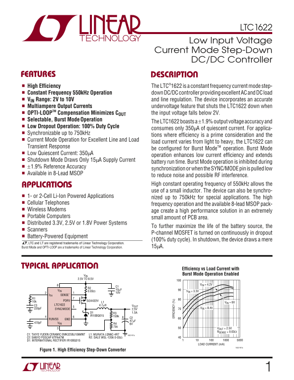
TYPICAL APPLICATIO
Efficiency vs Load Current with VIN Burst Mode Operation Enabled
2.5V TO 8.5V
VIN = 4.2V
VIN 10µF
0.03Ω VIN = 3.3V
ITH SENSE–
10k PDRV Si3443DV
L1 VIN = 6V
C3 LTC1622 4.7µH
220p F VIN = 8.4V
SYNC/MODE 2.5V
IR10BQ015 159k
RUN/SS GND
470p F VFB R4
VOUT = 2.5V RSENSE = 0.03Ω
C1: TAIYO YUDEN CERAMIC EMK325BJ106MNT L1: MURATA LQN6C-4R7 1622 F01a C2: SANYO POSCAP 6TPA47M R2: DALE WSL-1206 0-03Ω D1: INTERNATIONAL RECTIFIER IR10BQ015
LOAD CURRENT (m A)
Figure 1. High Efficiency Step-Down Converter
Page Summary Contents For LINEAR TECHNOLOGY LTC1622 Low Input Voltage Current Mode Step-Down DC DC Controller Data Sheet User Manual
Manual Details
| Brand | Current |
|---|---|
| Pages | 16 |
| File Size | 187.62 KB |
| Published | May 28, 2026 |
Enter the captcha to get the download link:

Frequently Asked Questions
How can I improve efficiency with fluctuating loads?
Utilize Burst Mode operation which enhances low current efficiency and extends battery run time.
What defines the minimum working input voltage?
The LTC1622 is rated to operate with an input voltage range from 2V up to 10V.
How much power does the unit consume when deactivated?
In shutdown mode, the device draws a very low amount of current: approximately 15mA.
What protection mechanism guards against low input voltage?
The incorporated undervoltage feature automatically shuts the LTC1622 down if the input falls below 2V.