# A B C D E F G H I J K L M N O P Q R S T U V W X Y Z

ST AN3261 Application Note - Dual Push-Button Smart Reset Devices with User_Adjustable Setup Delays

Summary

Enhance your system reliability with Smart Reset™ devices. This solution provides stable hardware resetting by requiring continuous press activation from dual or multiple input buttons, eliminating bulky physical reset holes. Developed for electronics engineers, this guide details the comprehensive features—including adjustable delays and voltage monitoring—and offers application diagrams that walk users through implementing robust, dependable power-on reset mechanisms in complex embedded systems.
📄 Preview 📖 Table of Contents Contents PAGE OF 17

Page 1 Text Content

AN3261

Application note

Dual push-button Smart Reset™ devices with user-adjustable setup delays

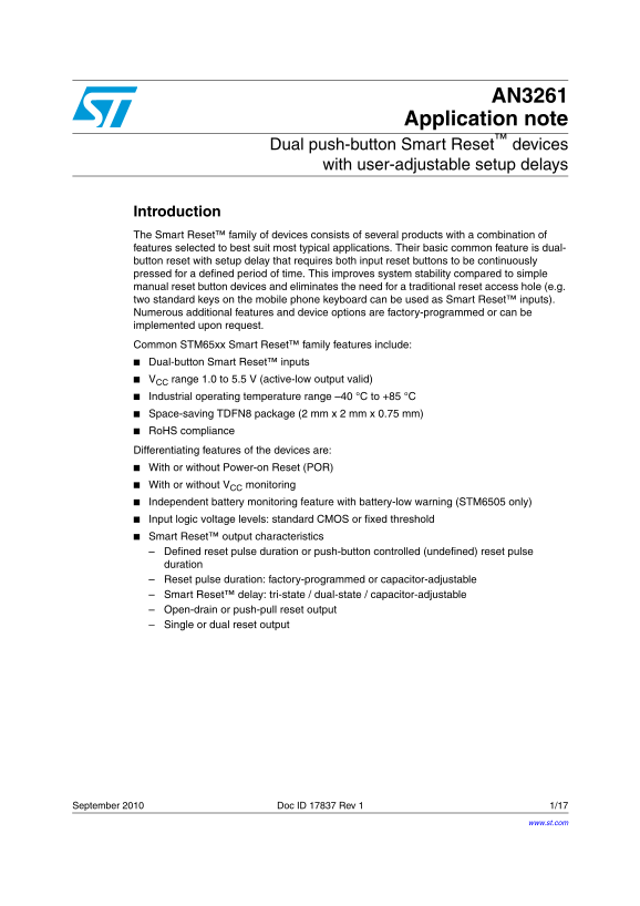
Introduction The Smart Reset™ family of devices consists of several products with a combination of features selected to best suit most typical applications. Their basic common feature is dual- button reset with setup delay that requires both input reset buttons to be continuously pressed for a defined period of time. This improves system stability compared to simple manual reset button devices and eliminates the need for a traditional reset access hole (e.g. two standard keys on the mobile phone keyboard can be used as Smart Reset™ inputs). Numerous additional features and device options are factory-programmed or can be implemented upon request. Common STM65xx Smart Reset™ family features include: Dual-button Smart Reset™ inputs VCC range 1.0 to 5.5 V (active-low output valid) Industrial operating temperature range –40 °C to +85 °C Space-saving TDFN8 package (2 mm x 2 mm x 0.75 mm) Ro HS compliance Differentiating features of the devices are: With or without Power-on Reset (POR) With or without VCC monitoring Independent battery monitoring feature with battery-low warning (STM6505 only) Input logic voltage levels: standard CMOS or fixed threshold Smart Reset™ output characteristics Defined reset pulse duration or push-button controlled (undefined) reset pulse duration Reset pulse duration: factory-programmed or capacitor-adjustable Smart Reset™ delay: tri-state / dual-state / capacitor-adjustable Open-drain or push-pull reset output Single or dual reset output

September 2010 Doc ID 17837 Rev 1 1/17

www.st.com

Page Summary Contents For ST AN3261 Application Note - Dual Push-Button Smart Reset Devices with User_Adjustable Setup Delays

Page 1 AN3261 Application note Dual push-button Smart Reset™ devices with user-adjustable setup delays Introduction The Smart Reset™ family of devices consists of several products with a combination of featu...
Page 2 Contents AN3261 Contents Features . . . . . . . . . . . . . . . . . . . . . . . . . . . . . . . . . . . . . . . . . . . . . . . . . . . 4 Typical application diagrams . . . . . . . . . . . . . . . . ....
Page 3 AN3261 List of figures List of figures Figure 1. Single-button Smart Reset™ typical application diagram, with “early-warning” feature, STM6503 . . . . . . . . . . . . . . . . . . . . . . . . . . . . ....
Page 4 Features AN3261 1 Features The Smart Reset™ functionality is a feature that introduces a reset output response delay. Both of the Smart Reset™ input buttons must be pressed for a defined t SRC period,...
Page 5 AN3261 Typical application diagrams 2 Typical application diagrams The STM65xx family of Smart Reset™ products provides a broad variety of options for various types of applications. 2.1 Single-button ...
Page 6 Typical application diagrams AN3261 Figure 2. Timing diagram - single push-button Smart Reset™ t SRC t REC 6/17 Doc ID 17837 Rev 1
Page 7 AN3261 Typical application diagrams 2.2 Dual-button reset The most frequent application requires a configuration with two reset buttons which further improves immunity to undesired resets by adding a ...
Page 8 Typical application diagrams AN3261 2.3 Multiple-button reset Adding even more input buttons is possible by adding a simple OR gate. All of the buttons must then be pressed simultaneously for at least...
Page 9 AN3261 Typical application diagrams Figure 6. Timing diagram - three push-button Smart Reset™ t SRC Push- button 1 Push- button 2 Push- button 3 t REC 2.4 Input pull-up considerations (CMOS/fixed leve...
Page 10 Typical application diagrams AN3261 2.6 Reliability note Devices with timings adjusted by external components vs. environmental considerations For device options with timings (t SRC, t REC) adjusted b...
Page 11 AN3261 Demonstration boards, promotion tools 3 Demonstration boards, promotion tools A complete set of demonstration/promotion tools is available for various purposes, from easy, high-level applicatio...
Page 12 Demonstration boards, promotion tools AN3261 3.2 STM65xx interposer boards Purpose The dedicated interposer PC boards were created for each STM65xx Smart Reset™ device for a quick and flexible applica...
Page 13 AN3261 Demonstration boards, promotion tools 3.3 Smartphone demonstration example Purpose The STM65xx smartphone demonstration shows the Smart Reset™ concept and functionality in a real application (d...
Page 14 Demonstration boards, promotion tools AN3261 Smart Reset™ concept demonstration Push ON/OFF button → goes into a normal ON state (amber display backlight on) Push stuck button → goes into stuck mode t...
Page 15 AN3261 Conclusion 4 Conclusion The family of Smart Reset™ devices provides a variety of smartphone or PDA hardware reset solutions, some examples of which are shown in this application note, others ar...
Page 16 Revision history AN3261 5 Revision history Table 1. Document revision history Date Revision Changes 22-Sep-2010 Initial release. 16/17 Doc ID 17837 Rev 1
Page 17 AN3261 Please Read Carefully: Information in this document is provided solely in connection with ST products. STMicroelectronics NV and its subsidiaries (“ST”) reserve the right to make changes, corre...

Manual Details

Brand Dual
Pages 17
File Size 630.21 KB
Published June 03, 2026
47 views

Enter the captcha to get the download link:

captcha

Frequently Asked Questions

How does the Smart Reset feature improve system stability?

It requires both input reset buttons to be continuously pressed for a defined period of time, which enhances stability compared to simple manual button devices.

What are the operational voltage and temperature limits?

The V range is 1.0 to 5.5 V (active-low output valid), and it operates in an industrial temperature range from –40 °C to +85 °C.

Can I integrate this with a smartphone or existing keypad inputs?

Yes, standard keys, such as those on a mobile phone keyboard, can be utilized as Smart Reset™ input buttons.

How adjustable is the reset delay and pulse duration?

The Smart Reset delay can be tri-state/dual-state/capacitor-adjustable, and both the reset pulse duration and the overall delay period are configurable.