SIEMENS SMBTA 55 SMBTA 56 DATA SHEET
Summary
These PNP Silicon AF Transistors are robust semiconductor components designed for critical switching and signal amplification applications in electronic circuits. Featuring high breakdown voltage and low collector-emitter/base saturation voltages, they ensure optimal performance and efficiency in sophisticated designs. The technical manual provides comprehensive specifications for engineers and designers, detailing maximum ratings, accurate DC and AC electrical characteristics, thermal parameters, and precise package information required for reliable circuit board integration.
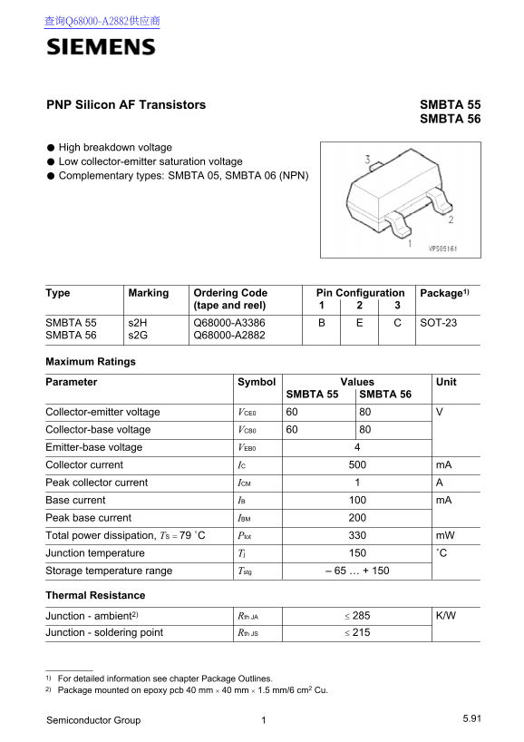
Page 1 Text Content
PNP Silicon AF Transistors SMBTA 55
SMBTA 56
High breakdown voltage Low collector-emitter saturation voltage Complementary types: SMBTA 05, SMBTA 06 (NPN)
Type Marking Ordering Code Package1)Pin Configuration
(tape and reel)
SMBTA 55 s2H Q68000-A3386 SOT-23 SMBTA 56 s2G Q68000-A2882
Maximum Ratings Parameter Symbol Values Unit
SMBTA 55 SMBTA 56
Collector-emitter voltage VCE0 Collector-base voltage VCB0 Emitter-base voltage VEB0 Collector current IC m A Peak collector current ICM A1 Base current IB m A100 Peak base current IBM Total power dissipation, TS ˚C Ptot m W Junction temperature Tj ˚C Storage temperature range Tstg – 65 … + 150
Thermal Resistance
Junction - ambient2) Rth JA ≤ 285 K/W
Junction - soldering point Rth JS ≤ 215
1) For detailed information see chapter Package Outlines. 2) Package mounted on epoxy pcb 40 mm mm mm/6 cm2 Cu.
Semiconductor Group 5.91
Page Summary Contents For SIEMENS SMBTA 55 SMBTA 56 DATA SHEET
Manual Details
| Brand | Siemens |
|---|---|
| Pages | 4 |
| File Size | 146.75 KB |
| Published | June 02, 2026 |
Enter the captcha to get the download link:

Frequently Asked Questions
What is the difference in breakdown voltage between SMBTA 55 and SMBTA 56?
SMBTA 55 has a maximum collector-emitter breakdown voltage (VCEO) of 60V, while SMBTA 56 is rated at 80V.
What is the maximum allowable power dissipation for these components?
The maximum total power dissipation (Ptot) is listed as 330 mW for both types.
How low can the output capacitance be?
Under standard conditions, the output capacitance ($C_{obo}$) is measured at –12– pF when $V_{CB} = 10 V$ and $f = 1 MHz$.