# A B C D E F G H I J K L M N O P Q R S T U V W X Y Z

Siemens Fault Tolerant Differential CAN Transceiver TLE 6252 G User's Manual

Summary

This fault-tolerant differential CAN Transceiver, TLE 6252 G, is designed for reliable communication in demanding automotive and industrial environments. It serves as a critical interface between your CAN controller and the physical bus, supporting data rates up to 125 kBaud. The device automatically switches to single-wire mode upon detecting wiring failures and features low power consumption modes (Sleep/Standby) for enhanced efficiency. This manual provides comprehensive details, including pin definitions, functional block diagrams, operational failure management, and recommended test procedures for optimal integration into your system design.
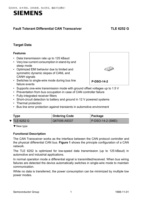
📄 Preview PAGE OF 25

Page 1 Text Content

Fault Tolerant Differential CAN Transceiver TLE 6252 G

Target Data

Features Data transmission rate up to 125 k Baud Very low current consumption in stand-by and sleep mode Optimized EMI behavior due to limited and symmetric dynamic slopes of CANL and CANH signals Switches to single-wire mode during bus line

P-DSO-14-2

failure events Supports one-wire transmission mode with ground offset voltages up to 1.5 V Preventation from bus occupation in case of CAN controller failure Fully-integrated receiver filters Short-circuit detection to battery and ground in 12 V powered systems Thermal protection Bus line error protection against transients in automotive environment

Type Ordering Code Package TLE 6252 G Q67006-A9337 P-DSO-14-2 (SMD) ▼ New type

Functional Description The CAN Transceiver works as the interface between the CAN protocol controller and the physical differential CAN bus. Figure 1 shows the principle configuration of a CAN network. The TLE 6252 is optimized for low-speed data transmission (up to 125 k Baud) in automotive and industrial applications. In normal operation mode a differential signal is transmitted/received. When bus wiring failures are detected the device automatically switches in single-wire mode to maintain communication. While no data is transferred, the power consumption can be minimized by multiple low power modes.

Semiconductor Group 1998-11-01

Page Summary Contents For Siemens Fault Tolerant Differential CAN Transceiver TLE 6252 G User's Manual

Page 1 Fault Tolerant Differential CAN Transceiver TLE 6252 G Target Data Features Data transmission rate up to 125 k Baud Very low current consumption in stand-by and sleep mode Optimized EMI behavior due t...
Page 2 TLE 6252 G Local Area 1 Local Area 2 Controller 1 Controller 2 Rx D Tx D Tx D 2Rx D2 Transceiver 1 Transceiver 2 Bus Line AES02410 Figure 1 CAN Network Example Semiconductor Group 1998-11-01
Page 3 TLE 6252 G Pin Configuration (top view) P-DSO-14-2 INH BATV Tx D GND Rx D CANL NERR CANH NSTB CCV ENT RTL WAKE RTH AEP02411 Figure 2 Semiconductor Group 1998-11-01
Page 4 TLE 6252 G Table 1 Pin Definitions and Functions Pin No. Symbol Function INH Inhibit output; For controlling an external 5 V regulator Tx D Transmit data input; LOW: bus is dominant, HIGH: bus is rece...
Page 5 TLE 6252 G Functional Block Diagram VBATCC RTL L Termination CANH Driver Failure Temperature Tx D Management Protection RTH H Termination Output Filter Stage Receiver Failure Detect Wake - Up NERR Tim...
Page 6 TLE 6252 G General Operation Modes In addition to the normal operation mode, the CAN transceiver offers three multiple low power operation modes to save power when there is no bus achieved: sleep mode...
Page 7 TLE 6252 G Table 2 Truth Table of the CAN Transceiver NSTB ENT Mode INH NERR Rx D RTL VBAT stand-by 1) Vbat active LOW wake-up interrupt if switched VCC is present to VBAT sleep mode 2) floating switc...
Page 8 TLE 6252 G Normal Operation NSTB ENT INH HIGH11 NSTB = 0 ENT (NSTB = 0 ENT ENT = 0) VCC or CC NSTB VCC 1= Stand-By Stand-By CCV NSTB ENT INH NSTB ENT INH NSTB 0 or HIGH1 =CC HIGH NSTB =ENT ENT 0ENT (W...
Page 9 TLE 6252 G Bus Failure Management The TLE 6252 detects the bus failures as described in the following (Table 3, failures listed according to ISO 11519-2) and automatically switches to a dedicated CANH...
Page 10 TLE 6252 G Table 3 Specified Wiring Failure Cases on the Bus Line 1) (according to ISO 11519-2) CANH CANL Wire Interrupted Failure case 2: Failure case 1: CCV CCV CANL CANL Tx D1 Rx D Tx D1 Rx D CANH ...
Page 11 TLE 6252 G Table 3 Specified Wiring Failure Cases on the Bus Line (cont’d) 1) (according to ISO 11519-2) CANH CANL Wire Short-Circuited to Battery Failure case 6: > 7.2 V Failure case 3: > 7.2 V...
Page 12 TLE 6252 G Circuit Protection A current limiting circuit protects the CAN transceiver output stages from damage by short-circuit to positive and negative battery voltages. The CANH and CANL pins are p...
Page 13 TLE 6252 G Operating Range Parameter Symbol Limit Values Unit Notes min. max. Logic input voltage VCC 4.75 5.25 Battery input voltage VBAT Junction temperature Tj – 40 °C Thermal Resistance Junction a...
Page 14 TLE 6252 G Static Characteristics 4.75 VCC 5.25 V; VNSTB VCC; 6 VBAT V; – Tj °C (unless otherwise specified). All voltages are defined with respect to ground. Positive current flowing into the IC. Par...
Page 15 TLE 6252 G Static Characteristics (cont’d) 4.75 VCC 5.25 V; VNSTB VCC; 6 VBAT V; – Tj °C (unless otherwise specified). All voltages are defined with respect to ground. Positive current flowing into th...
Page 16 TLE 6252 G Static Characteristics (cont’d) 4.75 VCC 5.25 V; VNSTB VCC; 6 VBAT V; – Tj °C (unless otherwise specified). All voltages are defined with respect to ground. Positive current flowing into th...
Page 17 TLE 6252 G Static Characteristics (cont’d) 4.75 VCC 5.25 V; VNSTB VCC; 6 VBAT V; – Tj °C (unless otherwise specified). All voltages are defined with respect to ground. Positive current flowing into th...
Page 18 TLE 6252 G Static Characteristics (cont’d) 4.75 VCC 5.25 V; VNSTB VCC; 6 VBAT V; – Tj °C (unless otherwise specified). All voltages are defined with respect to ground. Positive current flowing into th...
Page 19 TLE 6252 G Static Characteristics (cont’d) 4.75 VCC 5.25 V; VNSTB VCC; 6 VBAT V; – Tj °C (unless otherwise specified). All voltages are defined with respect to ground. Positive current flowing into th...
Page 20 TLE 6252 G Dynamic Characteristics VCC = 4.75 V to 5.25 V; VNSTB = VCC; VBAT = 6 V to 27 V; TA = – 40 to + 125 o C (unless otherwise specified). All voltages are defined with respect to ground. Positi...
Page 21 TLE 6252 G Dynamic Characteristics (cont’d) VCC = 4.75 V to 5.25 V; VNSTB = VCC; VBAT = 6 V to 27 V; TA = – 40 to + 125 o C (unless otherwise specified). All voltages are defined with respect to groun...
Page 22 TLE 6252 G Dynamic Characteristics (cont’d) VCC = 4.75 V to 5.25 V; VNSTB = VCC; VBAT = 6 V to 27 V; TA = – 40 to + 125 o C (unless otherwise specified). All voltages are defined with respect to groun...
Page 23 TLE 6252 G Test and Application NSTB Rx DNERR Tx DENTWAKE INH TLE 6252 CAN Transceiver RTH RTL CC CANH CANL GNDV BAT CAN Bus Substitute 1 Schaffner Generator CAN Bus Substitute 2 AES02423 Figure 5 Tes...
Page 24 TLE 6252 G C 505C / C 515C / C 164CJ TLE 4271 / TLE 4276 Microcontroller with On - Chip CAN Module Low Drop Voltage Regulator WAKE ENT NSTB NERR Rx D Tx D INH TLE 6252 CAN Transceiver RTH RTL CANH CAN...
Page 25 TLE 6252 G Package Outlines P-DSO-14-2 (Plastic Dual Small Outline) 1. ax Index Marking 1) Does not include plastic or metal protrusion of 0.15 max. per side 2) Does not include dambar protrusion of 0...

Manual Details

Brand Siemens
Pages 25
File Size 138.26 KB
Published June 02, 2026
68 views

Enter the captcha to get the download link:

captcha

Frequently Asked Questions

What is the maximum data transmission rate supported by this transceiver?

The data transmission rate can be up to 125 kBaud.

What action does the device take if bus wiring failures are detected?

It automatically switches to single-wire mode to maintain communication.

Which signal inputs control the power saving modes (sleep, stand-by)?

The operation modes are selected by the CAN controller via the NSTB and ENT inputs.

What protection features safeguard the unit in automotive environments?

It provides short-circuit detection to battery and ground, thermal protection, and bus line error protection.