ATMEL B10011S CAN Transceiver Data Manual
Summary
The B10011S is a robust CAN Transceiver optimized for vehicular applications, particularly interfacing between trucks and trailers. Key features include hardware fault recognition and versatile single-wire operation, ensuring uninterrupted data transmission even when wires are damaged or exposed to high electromagnetic interference. This manual provides engineers with comprehensive technical details, including operating modes, electrical specifications, block diagrams, and integration guidelines needed to reliably implement this industrial-grade transceiver into embedded automotive systems.
Page 1 Text Content
CAN Transceiver
Description The device B10011S is a transceiver for CAN bus systems This device contains a fault recognition circuit for faults with high transmission levels according to on one of the two wires which are normally used for trans- ISO WD 11992-1 (point-to-point interface between mission. If a fault occurs on one of the wires, the operation trucks and trailers). The special features of a circuit can be switched from double-wire to single-wire mode, containing this device allow transmission which is thus allowing proper operation even if one wire is broken, insensitive to electromagnetic interference that can has a short-cut or a high series resistance. appear particularly in truck applications, where, due to the length of the wires, high common-mode voltages (e.g., 50 V) can be coupled into the lines.
Features Benefits
The CAN driver B10011S is a low-speed, high-level Systems which employ this device have the following interface for 24-V (27-V) operation. It is developed for benefits in comparison with solutions using discrete signal levels of 8/16 V and a speed of up to 250 kbits/s. components:
Special features are:
Capability of single-wire operation
Especially suited for truck and van applications Hardware fault recognition
Interface between truck and trailer Inputs with high common-mode and differential- mode interference rejection above 100 VPP due to
Interface between dashboard and engine
external filters at the receiver input
High reliability Immunity against electromagnetic interference
Low cost Immunity against ground-voltage offsets < 6 V Ruggedized against ESD by MIL-STD-883C, method 3015
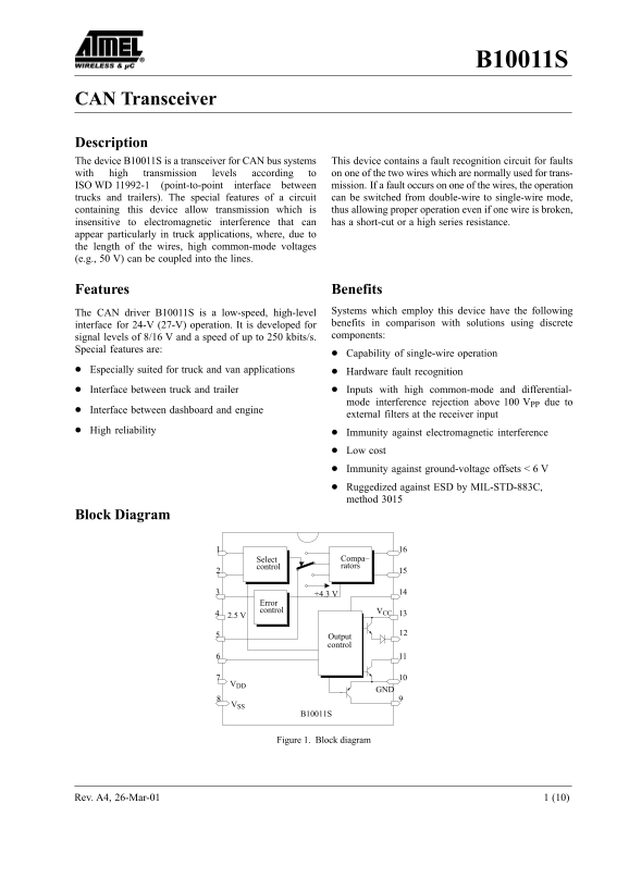
Block Diagram
Select Compa– control rators
Error control VCC 2.5 V
Output control
Figure 1. Block diagram
Rev. A4, 26-Mar-01 1 (10)
Page Summary Contents For ATMEL B10011S CAN Transceiver Data Manual
Manual Details
| Brand | Atmel |
|---|---|
| Pages | 10 |
| File Size | 69.40 KB |
| Published | May 15, 2026 |
Enter the captcha to get the download link:

Frequently Asked Questions
Does this device support single or double-wire operation?
It has the capability to switch from two-wire mode to a stable single-wire mode, maintaining operation even if one wire is broken.
What kinds of environments is this transceiver designed for?
It is especially suited for truck and van applications due to its high reliability and immunity against electromagnetic interference.
How does the device handle line faults?
It features hardware fault recognition, allowing it to detect interruptions, shorts to ground/V, or H to L shorts, signaling an error via the ER output.