SIEMENS TLE 4202 B Data Sheet
Summary
The TLE 4202B is a robust DC Motor Driver IC featuring two power comparators, capable of driving motors up to 2A. It integrates critical protection mechanisms, including free-wheeling diodes and short-circuit proofing to ground, ensuring reliability in challenging environments. This chip is primarily designed for demanding automotive and electric vehicle applications, operating safely across a wide temperature range from -40°C to 130°C. The manual provides comprehensive documentation on its pin functions, electrical characteristics, switching times, and detailed application circuit designs.
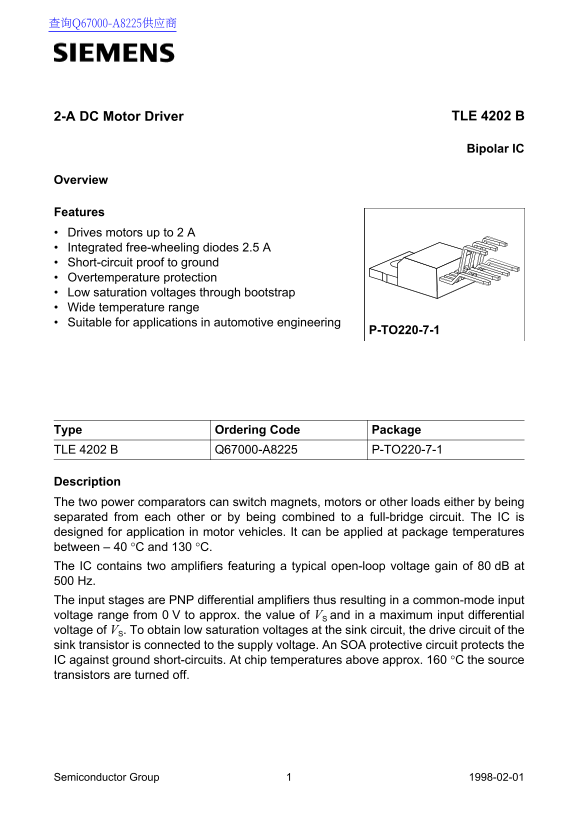
Page 1 Text Content
2-A DC Motor Driver TLE 4202 B
Bipolar IC
Overview
Features Drives motors up to 2 A Integrated free-wheeling diodes 2.5 A Short-circuit proof to ground Overtemperature protection Low saturation voltages through bootstrap Wide temperature range Suitable for applications in automotive engineering
P-TO220-7-1
Type Ordering Code Package TLE 4202 B Q67000-A8225 P-TO220-7-1
Description The two power comparators can switch magnets, motors or other loads either by being separated from each other or by being combined to a full-bridge circuit. The IC is designed for application in motor vehicles. It can be applied at package temperatures between – 40 °C and 130 °C. The IC contains two amplifiers featuring a typical open-loop voltage gain of 80 d B at Hz. The input stages are PNP differential amplifiers thus resulting in a common-mode input voltage range from 0 V to approx. the value of VS and in a maximum input differential voltage of VS. To obtain low saturation voltages at the sink circuit, the drive circuit of the sink transistor is connected to the supply voltage. An SOA protective circuit protects the IC against ground short-circuits. At chip temperatures above approx. 160 °C the source transistors are turned off.
Semiconductor Group 1998-02-01
Page Summary Contents For SIEMENS TLE 4202 B Data Sheet
Manual Details
| Brand | Siemens |
|---|---|
| Pages | 14 |
| File Size | 79.96 KB |
| Published | June 02, 2026 |
Enter the captcha to get the download link:

Frequently Asked Questions
What is the operating temperature range for this IC?
The device can operate at package temperatures between –40 °C and 130 °C.
Is the circuit protected against short circuits?
Yes, it includes an SOA protective circuit against ground short-circuits, and the outputs are inherently short-circuit proof to ground.
What type of power supply must be used for stable operation?
The standard operating range for the supply voltage (V S) is 3.5V to 17V.
How should I connect a decoupling capacitor?
A ceramic capacitor of at least 100 nF, blocking to ground, must be placed directly at the IC pins.