Siemens BGA 310 Data Sheet
Summary
This detailed datasheet provides comprehensive technical specifications for the BGA 310 Silicon Bipolar MMIC-Amplifier, an essential component for high-frequency RF applications. The manual covers electrical characteristics, s-parameters analysis over a wide frequency range (DC to 10 GHz), maximum operational limits, and recommended biasing circuits. It is designed for professional RF engineers and electronics designers building compact communication systems needing reliable amplification and low noise performance within a small package footprint.
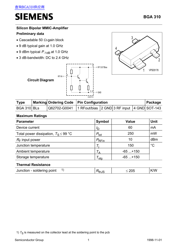
Page 1 Text Content
查询BGA310供应商
BGA 310
Silicon Bipolar MMIC-Amplifier Preliminary data • Cascadable 50 Ω-gain block • 9 d B typical gain at 1.0 GHz • 9 d Bm typical P-1d B at 1.0 GHz • 3 d B-bandwidth: DC to 2.4 GHz
RF OUT/Bias
VPS05178
RF IN
Circuit Diagram
EHA07312
Type Marking Ordering Code Pin Configuration Package BGA 310 BLs Q62702-G0041 1 RFout/bias 2 GND 3 RF input 4 GND SOT-143
Maximum Ratings Parameter Value Symbol Unit Device current ID m A60
Total power dissipation, TS ≤ 99 °C 250Ptot m W
RF input power d Bm10PRFin Tj Junction temperature °C
Ambient temperature TA -65 ...+150 Storage temperature Tstg -65 ...+150
Thermal Resistance
Junction - soldering point 1) Rth JS ≤ 205 K/W
1) TS is measured on the collector lead at the soldering point to the pcb
Semiconductor Group Sep-04-19981 Semiconductor Group 1998-11-01
Page Summary Contents For Siemens BGA 310 Data Sheet
Manual Details
| Brand | Siemens |
|---|---|
| Pages | 4 |
| File Size | 25.07 KB |
| Published | June 06, 2026 |
Enter the captcha to get the download link:

Frequently Asked Questions
What operational temperature range does this component support?
The device operates across a wide temperature range of -65 to +150 °C.
What is the minimum required bias voltage (V CC)?
The typical biasing configuration requires a minimum V CC of 7V.
What is the typical insertion power gain measured at 1.0 GHz?
The typical |S21| insertion power gain listed for 1.0 GHz is 9 dB.