ROHM US6T6 Product Specifications Data Sheet
Summary
This comprehensive datasheet details the US6T6 transistor, a reliable component designed for low-frequency amplification and driving applications. The manual provides engineers with essential technical information, including absolute maximum ratings, detailed electrical characteristics (such as collector-emitter saturation voltage, transition frequency, and current gain), switching times, and performance curves. Ideal for electronic designers building circuits that require stable, high-performance output amplification capability.
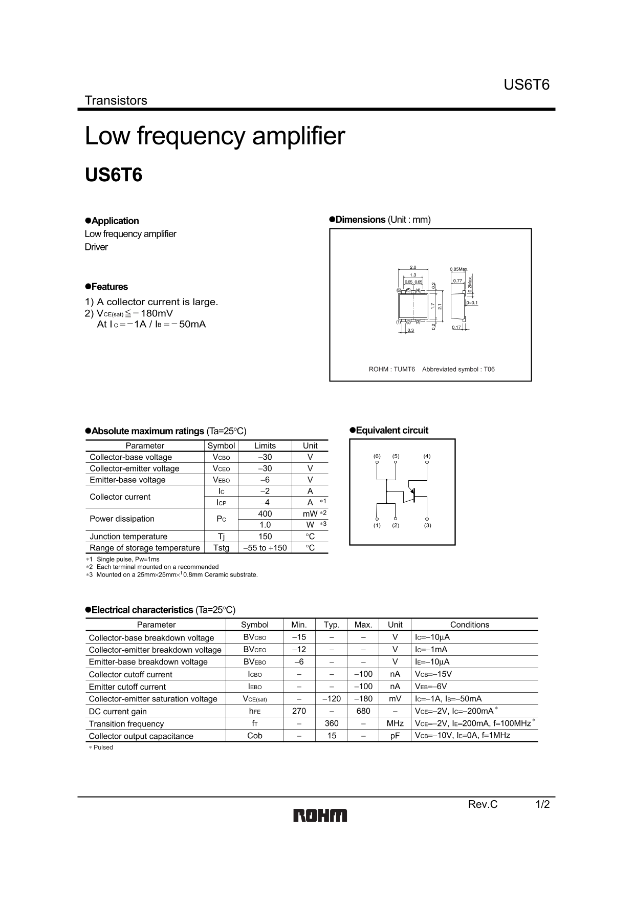
Page 1 Text Content
US6T6
Transistors
Low frequency amplifier US6T6
Application Dimensions (Unit : mm)
Low frequency amplifier Driver
Features 1) A collector current is large. 2) VCE(sat) − 180m V At I C = − 1A / IB = − 50m A
ROHM : TUMT6 Abbreviated symbol : T06
Absolute maximum ratings (Ta=25°C) Equivalent circuit
Parameter Symbol Limits Unit
Collector-base voltage VCBO −30 (4)(5)(6)
Collector-emitter voltage VCEO −30 0. 2M ax Emitter-base voltage VEBO −6 IC −2
Collector current
ICP −4 ∗1 m W ∗2
Power dissipation PC
Junction temperature Tj °C Range of storage temperature Tstg −55 to +150 °C
∗1 Single pulse, Pw=1ms Each terminal mounted on a recommended∗2 Mounted on a 25mm×25mm× 0.8mm Ceramic substrate.∗3
Electrical characteristics (Ta=25°C)
Parameter Symbol Min. Typ. Max. Unit Conditions
Collector-base breakdown voltage BVCBO −15 IC=−10µA Collector-emitter breakdown voltage BVCEO −12 IC=−1m A Emitter-base breakdown voltage BVEBO −6 IE=−10µA
Collector cutoff current ICBO −100 n A VCB=−15V Emitter cutoff current IEBO −100 n A VEB=−6V Collector-emitter saturation voltage VCE(sat) −120 −180 m V IC=−1A, IB=−50m A
DC current gain h FE VCE=−2V, IC=−200m A
Transition frequency f T MHz VCE=−2V, IE=200m A, f=100MHz Collector output capacitance Cob p F VCB=−10V, IE=0A, f=1MHz
∗ Pulsed
Rev.C 1/2
Page Summary Contents For ROHM US6T6 Product Specifications Data Sheet
Manual Details
| Brand | ROHM |
|---|---|
| Pages | 3 |
| File Size | 63.05 KB |
| Published | July 12, 2026 |
Enter the captcha to get the download link:

Frequently Asked Questions
What is the allowable storage temperature range for this transistor?
The range of storage temperature (Tstg) is between -55 to +150°C.
What substrate size must the component be mounted on?
It must be mounted on a ceramic substrate measuring 25mm × 25mm × 0.8mm.
What is the maximum rated collector current (Ic)?
The absolute maximum rating for the collector current (Ic) is -2 A.
Can this transistor be used in critical, life-sustaining equipment?
No, users must consult a sales representative if using it with machinery that requires extremely high reliability, such as medical or aerospace devices.