RoHM BD6722FS Data Manual/Specifications Sheet
Summary
This single-phase full-wave motor driver IC offers precise speed control via DC/PWM input and integrated current limiting for fan motors. The comprehensive manual provides detailed electrical characteristics, operating conditions, block diagrams, and critical usage cautions—including guidelines on thermal design and grounding potentials. It is designed for engineers developing reliable electronic systems that require high-performance motor control solutions.
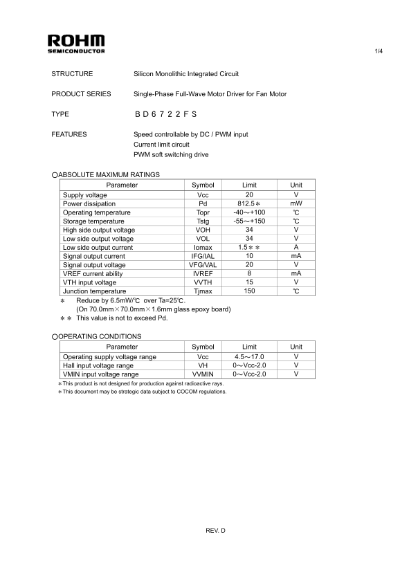
Page 1 Text Content
STRUCTURE Silicon Monolithic Integrated Circuit
PRODUCT SERIES Single-Phase Full-Wave Motor Driver for Fan Motor
TYPE BD6722FS
FEATURES Speed controllable by DC / PWM input Current limit circuit PWM soft switching drive
〇ABSOLUTE MAXIMUM RATINGS
Parameter Symbol Limit Unit
Supply voltage Vcc 20 V Power dissipation Pd 812.5* m W Operating temperature Topr -40~+100 ℃ Storage temperature Tstg -55~+150 ℃ High side output voltage VOH 34 V Low side output voltage VOL 34 V Low side output current Iomax 1.5** A Signal output current IFG/IAL 10 m A
Signal output voltage VFG/VAL 20 V
VREF current ability IVREF 8 m A VTH input voltage VVTH 15 V Junction temperature Tjmax 150 ℃ * Reduce by 6.5m W/℃ over Ta=25℃. (On 70.0mm×70.0mm×1.6mm glass epoxy board) ** This value is not to exceed Pd.
〇OPERATING CONDITIONS
Parameter Symbol Limit Unit
Operating supply voltage range Vcc 4.5~17.0 V Hall input voltage range VH 0~Vcc-2.0 V VMIN input voltage range VVMIN 0~Vcc-2.0 V *This product is not designed for production against radioactive rays. *This document may be strategic data subject to COCOM regulations.
REV. D
Page Summary Contents For RoHM BD6722FS Data Manual/Specifications Sheet
Manual Details
| Brand | ROHM |
|---|---|
| Pages | 5 |
| File Size | 143.37 KB |
| Published | June 15, 2026 |
Enter the captcha to get the download link:

Frequently Asked Questions
What is the operational supply voltage range for this motor driver?
The operating supply voltage (Vcc) ranges from 4.5 V to 17.0 V.
How should I prevent damage during overvoltage conditions?
If you expect to exceed absolute maximum ratings, such as the supply voltage, consider adding circuit protection devices like fuses.
Can this device handle high electromagnetic vibrations?
The product is not designed for production against radioactive rays. Use careful thermal and electrical design safety measures in your equipment.
What precaution should be taken concerning ground (GND) potential?
Ensure that the GND pin maintains minimum potential, and all other terminals do not fall below GND voltage due to back electromotive force or transients.