ROHM TT8M1 Data Handbook/Specifications Manual
Summary
This dual MOSFET package delivers high-efficiency power switching through both N-channel and P-channel transistors in a robust TSST8 housing. Featuring low on-resistance and simple 1.5V drive capability, it is ideal for engineers designing general electronic equipment needing reliable, high-power handling. The accompanying manual provides thorough technical data, including structural dimensions, absolute maximum ratings, detailed electrical characteristics curves, and full operational specifications required for precise circuit integration.
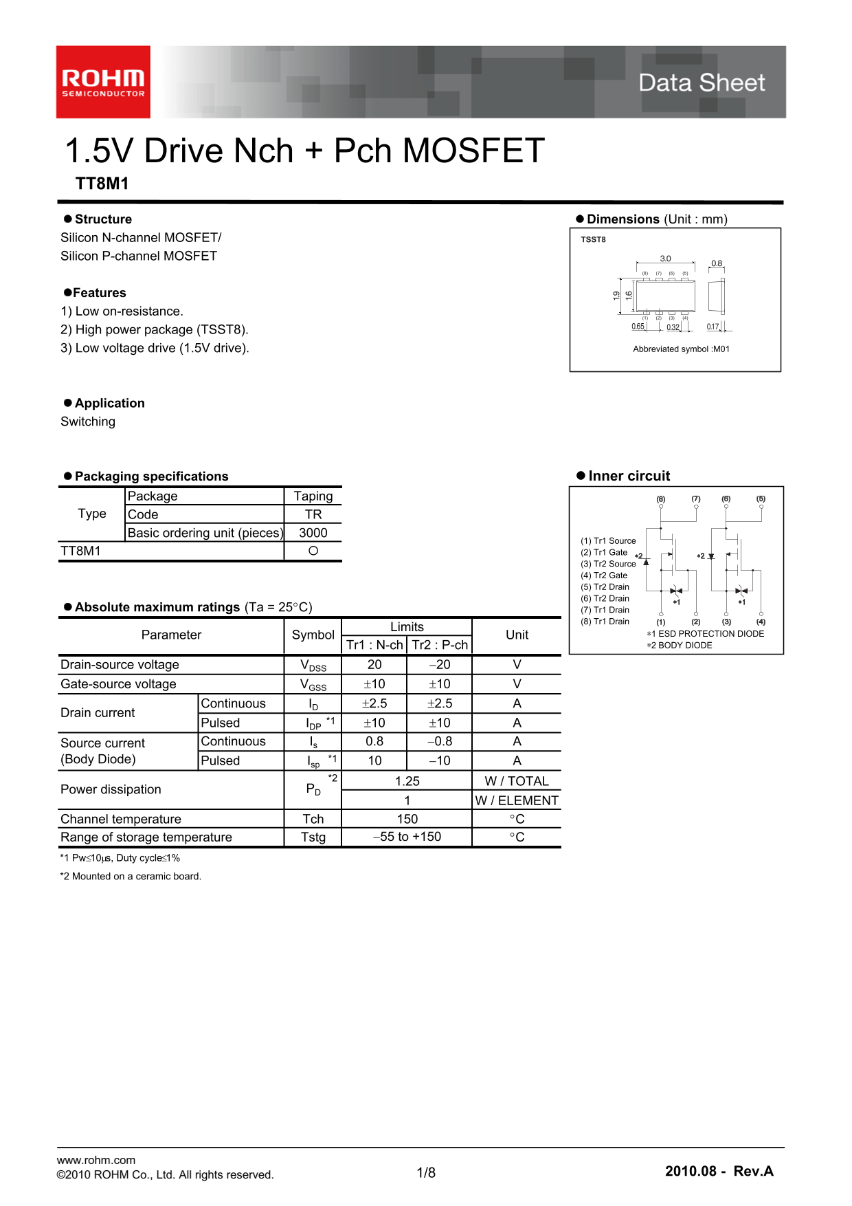
Page 1 Text Content
1.5V Drive Nch + Pch MOSFET TT8M1 Structure Dimensions (Unit : mm) Silicon N-channel MOSFET/ TSST8 Silicon P-channel MOSFET
Features 1) Low on-resistance.
2) High power package (TSST8).
3) Low voltage drive (1.5V drive). Abbreviated symbol :M01
Application Switching
Packaging specifications Inner circuit
Package Taping Type Code TR Basic ordering unit (pieces)
(1) Tr1 Source TT8M1 (2) Tr1 Gate (3) Tr2 Source (4) Tr2 Gate (5) Tr2 Drain (6) Tr2 Drain
Absolute maximum ratings (Ta = 25C) (7) Tr1 Drain
(8) Tr1 Drain
Limits
Parameter Symbol Unit ∗1 ESD PROTECTION DIODE Tr1 : N-ch Tr2 : P-ch ∗2 BODY DIODE
Drain-source voltage VDSS 20
Gate-source voltage VGSS 10 10 Continuous ID 2.5 2.5
Drain current
Pulsed IDP *1 10 10 Source current Continuous Is 0.8 0.8 (Body Diode) Pulsed Isp *1 10 *2
1.25 W / TOTAL
Power dissipation PD
W / ELEMENT
Channel temperature Tch C
Range of storage temperature Tstg 55 to +150 C
*1 Pw10s, Duty cycle1%
*2 Mounted on a ceramic board.
www.rohm.com
©2010 ROHM Co., Ltd. All rights reserved. 1/8 2010.08 - Rev.A
Page Summary Contents For ROHM TT8M1 Data Handbook/Specifications Manual
Manual Details
| Brand | ROHM |
|---|---|
| Pages | 9 |
| File Size | 396.85 KB |
| Published | July 12, 2026 |
Enter the captcha to get the download link:
