Page 1
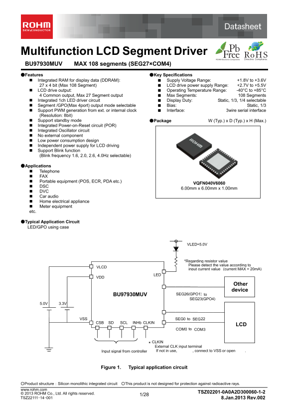
Datasheet Multifunction LCD Segment Driver BU97930MUV MAX 108 segments (SEG27×COM4) ●Features ●Key Specifications Integrated RAM for display data (DDRAM): ■ Supply Voltage Range: +1.8V to +3.6V 27 x 4...
Page 2
BU97930MUV MAX 108 segments (SEG27×COM4) Datasheet ●Block Diagram / Pin Configuration / Pin Description COM0……COM3 SEG0 …...22 SEG23...26 LED LCD voltage common Segment Segment LED G enerator driver d...
Page 3
BU97930MUV MAX 108 segments (SEG27×COM4) Datasheet ●Absolute Maximum Ratings (VSS=0V) Parameter Symbol Ratings Unit Remarks Power supply voltage 1 VDD -0.3 to +4.5 V Power supply Power supply voltage ...
Page 4
BU97930MUV MAX 108 segments (SEG27×COM4) Datasheet ●Electrical Characteristics – continued Oscillation Frequency Characteristics (Ta=-40°C to +85°C, VDD=1.8V to 3.6V, VLCD=2.7V to 5.5V, VSS=0) Limit P...
Page 5
BU97930MUV MAX 108 segments (SEG27×COM4) Datasheet ●I/O equivalent circuit VLCD VDD VSSVSS VDD VLCD SEG0-22 COM0-3 CSB, SD, SCL,INHb CLKIN VLCD LED SEG23-26 Figure 5. I/O equivalent circuit www.rohm.c...
Page 6
BU97930MUV MAX 108 segments (SEG27×COM4) Datasheet ●Example of recommended circuit 1) LED/GPO operation VLED =5. 0V *Regarding resistor value Please detect the value according to input current value (...
Page 7
BU97930MUV MAX 108 segments (SEG27×COM4) Datasheet ●Function description ○Command and data transfer method ○3-SPI (3-wire serial interface) This device is controlled by a 3-wire signal (CSB, SCL, and ...
Page 8
BU97930MUV MAX 108 segments (SEG27×COM4) Datasheet ○Write display data and transfer method This device has Display Data RAM (DDRAM) of 28×4=112bit. The relationship between data input and display data...
Page 9
BU97930MUV MAX 108 segments (SEG27×COM4) Datasheet ○Blink function This device has Blink function. Blink function can set each segment port individually. Blink ON/OFF and Blink frequency are set by th...
Page 10
BU97930MUV MAX 108 segments (SEG27×COM4) Datasheet ○LCD Driver Bias/Duty Circuit BU97930MUV generates LCD driving voltage using an on-chip Buffer AMP. Also, it can drive LCD with low power consumption...
Page 11
BU97930MUV MAX 108 segments (SEG27×COM4) Datasheet ●Command Descriptions D/C, Data / Command judgment bit (MSB) For more details, please refer to 3wire serial I/F ○Mode Set (MODESET) MSB LSB D/C D6 D5...
Page 12
BU97930MUV MAX 108 segments (SEG27×COM4) Datasheet ○Display control (DISCTL) MSB LSB D/C D6 D5 D4 D3 D2 D1 D0 Hex Reset 1st byte Command 1 0 0 0 0 0 1 0 82h - 2nd byte Command 0 0 0 0 P3 P2 P1 P0 - 02...
Page 13
BU97930MUV MAX 108 segments (SEG27×COM4) Datasheet ○Address set (ADSET) MSB LSB MSB D/C D6 D5 D4 D3 D2 D1 D0 Hex Reset 1st byte Command 1 0 0 0 0 0 1 1 83h - 2nd byte Command 0 0 0 P4 P3 P2 P1 P0 - 00...
Page 14
BU97930MUV MAX 108 segments (SEG27×COM4) Datasheet ○SEG/GPO port change (OUTSET) MSB LSB D/C D6 D5 D4 D3 D2 D1 D0 Hex Reset 1st byte Command 1 0 0 0 1 0 0 0 88h - 2nd byte Command 0 0 0 0 0 P2 P1 * - ...
Page 15
BU97930MUV MAX 108 segments (SEG27×COM4) Datasheet ○LED drive-control (PWM “H” width control) command (PWMSET) MSB LSB D/C D6 D5 D4 D3 D2 D1 D0 Hex Reset 1st byte Command 1 0 0 0 1 0 1 0 8Ah - 2nd byt...
Page 16
BU97930MUV MAX 108 segments (SEG27×COM4) Datasheet ○RAM WRITE (RAMWR) MSB LSB D/C D6 D5 D4 D3 D2 D1 D0 Hex Reset 1st byte Command 1 0 1 0 0 0 0 0 A0h - 2nd byte Command Display data Random …. n byte C...
Page 17
BU97930MUV MAX 108 segments (SEG27×COM4) Datasheet ○OSC external input command (OSCSET) MSB LSB D/C D6 D5 D4 D3 D2 D1 D0 Hex Reset 1st byte Command 1 0 0 1 1 0 0 0 98h - 2nd byte Command 0 0 0 0 0 P2 ...
Page 18
BU97930MUV MAX 108 segments (SEG27×COM4) Datasheet ○GPO output set command (GPOSET) MSB LSB D/C D6 D5 D4 D3 D2 D1 D0 Hex Reset 1st byte Command 1 0 0 1 1 0 1 0 9Ah - 2nd byte Command 0 0 0 P4 P3 P2 P1...
Page 19
BU97930MUV MAX 108 segments (SEG27×COM4) Datasheet ●LCD driving waveform 1/4Duty Line inversion Frame inversion SEGn SEGn+1 SEGn+2SEGn+3 SEGn SEGn+1 SEGn+2 SEGn+3 COM0 state A COM0 state A COM1 state ...
Page 20
BU97930MUV MAX 108 segments (SEG27×COM4) Datasheet 1/3Duty Line inversion Frame inversion SEGn SEGn+1 SEGn+2 SEGn+3 SEGn SEGn+1 SEGn+2 SEGn+3 COM0 state A COM0 state A COM1 state B COM1 state B COM2 C...
Page 21
BU97930MUV MAX 108 segments (SEG27×COM4) Datasheet 1/1Duty (Static) Line inversion Frame inversion SEGn SEGn+1 SEGn SEGn+1SEGn+2 SEGn+3 SEGn+2 SEGn+3 COM0 state A state B COM0 state A state B COM1 COM...
Page 22
BU97930MUV MAX 108 segments (SEG27×COM4) Datasheet ●Initialize Sequence Recommended input sequence is listed below, before starting LCD driving. (Refer to Power ON/OFF sequence) Input voltage supply C...
Page 23
BU97930MUV MAX 108 segments (SEG27×COM4) Datasheet ●Cautions on Power-On/ Power-Off condition ○POR circuit BU97930MUV has “P.O.R” (Power-On Reset) circuit and Software Reset function. Please follow th...
Page 24
BU97930MUV MAX 108 segments (SEG27×COM4) Datasheet ●Power ON / OFF sequence Display ON/OFF control by INHb terminal is not asynchronous with frame cycle. In order to prevent display flickering under t...
Page 25
BU97930MUV MAX 108 segments (SEG27×COM4) Datasheet ●Operational Notes (1) Absolute maximum ratings Operating the IC over the absolute maximum ratings may damage the IC. The damage can either be a shor...
Page 26
BU97930MUV MAX 108 segments (SEG27×COM4) Datasheet ●Ordering Information Part Number Package Packaging and forming specification MUV :VQFN040V6060 E2: Embossed tape and reel (VQFN040V6060) ●Marking Di...
Page 27
BU97930MUV MAX 108 segments (SEG27×COM4) Datasheet ●Physical Dimension, Tape and Reel Information Package Name VQFN040V6060 <Tape and Reel information> Embossed carrier tape Tape Quantity 2000pc...
Page 28
BU97930MUV MAX 108 segments (SEG27×COM4) Datasheet ●Revision History Date Revision Changes 14.Mar.2012 001 New Release Improved the statement in all pages. 8.Jan.2013 002 Deleted “Status of this docum...
Page 29
Datasheet Notice ●General Precaution 1) Before you use our Products, you are requested to carefully read this document and fully understand its contents. ROHM shall not be in any way responsible or li...
Page 30
Datasheet ●Precaution for Mounting / Circuit board design 1) When a highly active halogenous (chlorine, bromine, etc.) flux is used, the residue of flux may negatively affect product performance and r...
Page 31
Datasheet ●Other Precaution 1) The information contained in this document is provided on an “as is” basis and ROHM does not warrant that all information contained in this document is accurate and/or e...