ROHM IMT17 Product Data Sheet Manual
Summary
The IMT17 is a specialized dual transistor IC designed for general-purpose small signal amplifier applications. Featuring two independent chips in a compact, space-efficient SMT package with high collector current capability (-500mA), it minimizes board area and mounting costs. This manual provides comprehensive technical documentation, including absolute maximum ratings, detailed electrical characteristics (such as hFE and fT), and performance curves necessary for precise circuit integration. It is essential reference material for electronics engineers designing reliable and compact amplification circuits.
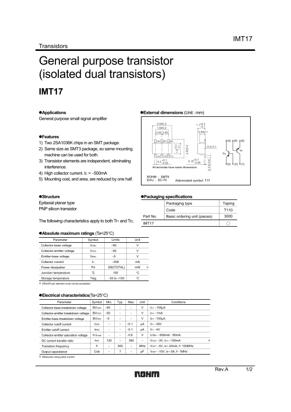
Page 1 Text Content
IMT17
Transistors
General purpose transistor (isolated dual transistors) IMT17 Applications External dimensions (Unit : mm) General purpose small signal amplifier
Features
1) Two 2SA1036K chips in an SMT package.
0 to 0.1
2) Same size as SMT3 package, so same mounting
machine can be used for both. (1)(2)(3)
3) Transistor elements are independent, eliminating 0.3
interference. All terminals have same dimensions
4) High collector current. IC = −500m A
ROHM : SMT6 1.
5) Mounting cost, and area, are reduced by one half. −0 .1
EIAJ : SC-74 Abbreviated symbol: T17
Structure Packaging specifications Epitaxial planar type Packaging type Taping
PNP silicon transistor 0. to .60.15−0.06
Code T110
Part No. 3000Basic ordering unit (pieces)
The following characteristics apply to both Tr1 and Tr2.
IMT17
Absolute maximum ratings (Ta=25°C)
Parameter Symbol Limits Unit
Collector-base voltage VCBO −60
Collector-emitter voltage VCEO −50 Emitter-base voltage VEBO −5
Collector current IC −500 m A Power dissipation Pd 300(TOTAL) m W
Junction temperature Tj °C Storage temperature Tstg −55 to +150 °C ∗ 200m W per element must not be exceeded.
Electrical characteristics(Ta=25°C)
Parameter Symbol Min. Typ. Max. Unit Conditions Collector-base breakdown voltage BVCBO −60 IC= −100µA
Collector-emitter breakdown voltage BVCEO −50 IC= −1m A Emitter-base breakdown voltage BVEBO −5 IE= −100µA
Collector cutoff current ICBO −0.1 µA V= −30V
Emitter cutoff current IEBO −0.1 µA V= −4V Collector-emitter saturation voltage VCE(sat) −0.6 IC/IB= −500m A/ −50m A DC current transfer ratio h FE VCE= −3V, IC= −100m A
Transition frequency f T MHz VCE= −5V, IE= 20m A, f= 100MHz
Output capacitance Cob p F VCB= −10V, IE= 0A, f= 1MHz
∗ Measured using pulse current.
Rev.A 1/2
Page Summary Contents For ROHM IMT17 Product Data Sheet Manual
Manual Details
| Brand | ROHM |
|---|---|
| Pages | 3 |
| File Size | 116.64 KB |
| Published | May 29, 2026 |
Enter the captcha to get the download link:

Frequently Asked Questions
What are the physical dimensions and mounting compatibility?
The external dimensions are 2.9±0.2 x 1.1−0.1 x 1.9±0.2 mm, and since they are the same size as SMT3 package, the Tr1/Tr2 machine can handle both.
What is the maximum allowable collector current?
The collector current (IC) is rated at up to -500 mA (total).
Are there limitations on power dissipation?
Power dissipation must not exceed 200mW per element, keeping the total within Pd 300(TOTAL) mW.
How should these transistors be used in critical applications?
If using them with equipment that requires an extremely high level of reliability and malfunction could endanger human life (e.g., medical or aerospace machinery), consult a sales representative first.