ROHM TCFG series P case User's Manual
Summary
The TCFG series offers high-reliability capacitors designed for critical applications in diverse electronic equipment, including audio-visual devices and communication gear. This manual provides comprehensive documentation covering electrical characteristics, dimensions, operational specifications, thermal shock resistance, and handling guidelines to ensure proper system integration. It is essential reading for electrical engineers and product designers seeking precise component data and performance assurance for their demanding electronics projects.
Page 1 Text Content
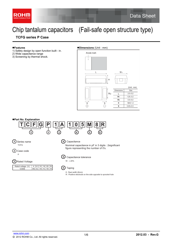
Chip tantalum capacitors (Fail-safe open structure type) TCFG series P Case
Features Dimensions (Unit : mm) 1) Safety design by open function built - in.
Anode mark
2) Wide capacitance range 3) Screening by thermal shock.
(Unit : mm) Dimensions Size
SS MAX.1.2 0.45 0.3+−
Part No. Explanation
Series name Capacitance
TCFG Nominal capacitance in p F in 3 digits : 2significant
figure representing the number of 0's.
Case code
Capacitance tolerance +− 20%M :
Rated Voltage
Rated voltage (V) 6.3
Taping
CODE 0G 0J 1A 1C 1D 1E
8 : Reel width (8mm) R : Positive electrode on the side opposite to sprocket hole
www.rohm.com
1/6 2012.03 - Rev.G
○c 2012 ROHM Co., Ltd. All rights reserved.
Page Summary Contents For ROHM TCFG series P case User's Manual
Manual Details
| Brand | ROHM |
|---|---|
| Pages | 7 |
| File Size | 155.62 KB |
| Published | May 27, 2026 |
Enter the captcha to get the download link:

Frequently Asked Questions
What types of critical equipment should not use these capacitors?
They are not designed for applications requiring extremely high reliability, such as medical instruments, aerospace machinery, or nuclear controllers.
What is the maximum rated operating temperature?
The overall operating range is -55°C to +125°C. However, full operation without voltage derating requires a max temperature of +85°C.
What are the recommended soldering conditions?
For wave soldering heat tests, the specified solder temperature is 260±10°C for a duration of 5±0.5s.
How durable are these capacitors against humidity changes?
The datasheet confirms moisture resistance after exposure to 90 to 95% RH at 60±2°C for over 500 hours.