ROHM TCO series B case User Guide Manual
Summary
These high-performance conductive polymer chip capacitors are designed for demanding electronic applications, featuring ultra-low ESR and enhanced resistance to thermal shock. The included manual provides comprehensive technical data sheets, detailed characteristic testing results (including temperature stability and moisture cycling), precise ratings tables, and clear product marking guidelines. This resource is essential for electrical engineers and designers requiring reliable, high-stability capacitor components for advanced consumer electronics, industrial control systems, and diverse power applications.
Page 1 Text Content
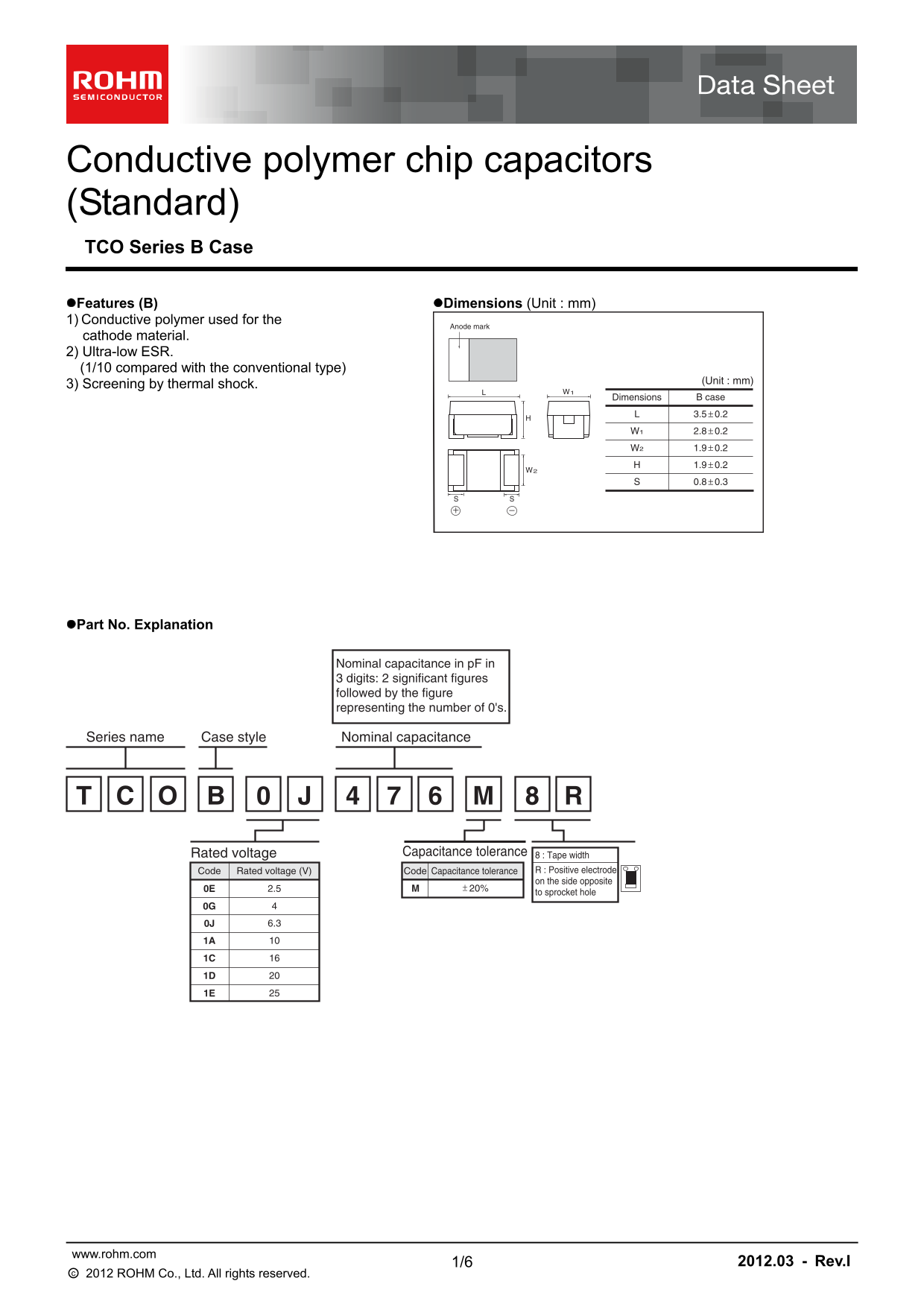
Conductive polymer chip capacitors (Standard) TCO Series B Case Features (B) Dimensions (Unit : mm) 1) Conductive polymer used for the
Anode mark
cathode material. 2) Ultra-low ESR. (1/10 compared with the conventional type)
(Unit : mm)
3) Screening by thermal shock.
Dimensions B case 3.5 0.2+−
Part No. Explanation
Nominal capacitance in p F in 3 digits: 2 significant figures followed by the figure representing the number of 0's.
Case style Series name Nominal capacitance
Rated voltage Capacitance tolerance 8 : Tape width
Code Rated voltage (V) Code Capacitance tolerance R : Positive electrode on the side opposite
to sprocket hole
www.rohm.com
1/6 2012.03 - Rev.I
○c 2012 ROHM Co., Ltd. All rights reserved.
Page Summary Contents For ROHM TCO series B case User Guide Manual
Manual Details
| Brand | ROHM |
|---|---|
| Pages | 7 |
| File Size | 127.25 KB |
| Published | July 12, 2026 |
Enter the captcha to get the download link:

Frequently Asked Questions
What is the operating temperature range for this capacitor?
The capacitor can operate between -55°C and +105°C.
Are these capacitors suitable for mission-critical applications like medical instruments?
No. They are not designed for equipment where failure could directly threaten human life, such as medical or aerospace machinery.
How is the capacitance value indicated on the body?
Capsitance is shown using a combination of codes that vary with the parts number and include both voltage and capacitance identifiers.
What is the recommended solder temperature range?
The suggested soldering temperature range is 240°C ± 5°C, with a duration of 10 to 0.5 seconds.