ROHM MCR03 User Guide
Summary
Discover the MCR03 series of compact thick film chip resistors, designed for reliable electronic applications up to 1/10W. This comprehensive manual details product specifications, including power derating curves, voltage ratings, and rigorous performance tests such as solderability and temperature endurance. Ideal for electronics designers and engineers who require high-quality, durable components for various machinery and consumer device manufacturing.
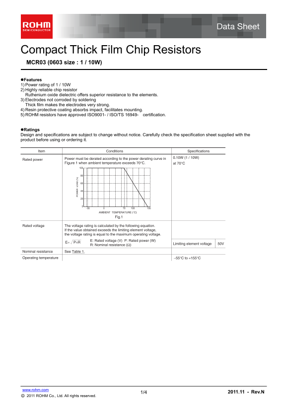
Page 1 Text Content
Compact Thick Film Chip Resistors MCR03 (0603 size : 1 / 10W) Features 1) Power rating of 1 / 10W 2) Highly reliable chip resistor Ruthenium oxide dielectric offers superior resistance to the elements. 3) Electrodes not corroded by soldering Thick film makes the electrodes very strong. 4) Resin protective coating absorbs impact, facilitates mounting. 5) ROHM resistors have approved ISO9001- / ISO/TS 16949- certification.
Ratings Design and specifications are subject to change without notice. Carefully check the specification sheet supplied with the product before using or ordering it.
Item Conditions Specifications
Rated power Power must be derated according to the power derating curve in Figure 1 when ambient temperature exceeds 70°C. at 70°C
AMBIENT TEMPERATURE (°C)
Fig.1
Rated voltage The voltage rating is calculated by the following equation.
If the value obtained exceeds the limiting element voltage, the voltage rating is equal to the maximum operating voltage.
E: Rated voltage (V) P: Rated power (W)
Limiting element voltage 50V
R: Nominal resistance (Ω)
Nominal resistance See Table 1. Operating temperature −55°C to +155°C
www.rohm.com
1/4 2011.11 - Rev.N
○c 2011 ROHM Co., Ltd. All rights reserved.
Page Summary Contents For ROHM MCR03 User Guide
Manual Details
| Brand | ROHM |
|---|---|
| Pages | 5 |
| File Size | 164.39 KB |
| Published | June 20, 2026 |
Enter the captcha to get the download link:

Frequently Asked Questions
Can these resistors be used in life-critical safety systems?
No, they are not designed for equipment requiring an extremely high level of reliability where failure could result in a direct threat to human life.
What must I do if the ambient temperature is above 70°C?
The rated power of the resistor must be derated according to the power derating curve provided in Figure 1.
What resistance tolerance options are available for MCR03?
Available tolerances include J (±5%), FX (±1%), and D (±0.5%).
Were there any recommended conditions for soldering the resistors?
Soldering should occur at 235±5°C or 260±5°C depending on the specific handling process, ensuring no remarkable abnormality.