ROHM EMT2, UMT2N, IMT2A Data Sheet User Manual
Summary
These dual general-purpose transistors (EMT2 / UMT2N / IMT2A) are essential power semiconductors designed for reliable operation in varied electronic applications, including audio and communication equipment. This comprehensive technical datasheet provides engineers with all necessary details, covering absolute maximum ratings, detailed electrical characteristics, performance curves (e.g., hFE, fT), and package specifications. Ideal for circuit designers who require high-performance, stable components for professional electronics development.
Page 1 Text Content
EMT2 / UMT2N / IMT2A
Transistors
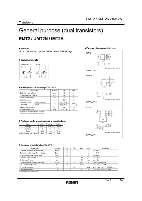
General purpose (dual transistors) EMT2 / UMT2N / IMT2A
Features External dimensions (Unit : mm)
1) Two 2SA1037AK chips in a EMT or UMT or SMT package.
(6) (1) Equivalent circuits 1.2 1.6
EMT2 / UMT2N IMT2A
Each lead has same dimensions
ROHM : EMT6
Tr1 Tr1 Tr2 Tr2
UMT2N
Absolute maximum ratings (Ta=25°C)
Parameter Symbol Limits Unit
Collector-base voltage VCBO −60 Collector-emitter voltage VCEO −50
0. 0. 0.1Min.
Emitter-base voltage VEBO −6 0. 0.
Each lead has same dimensions
Collector current IC −150 m A
ROHM : UMT6
Collector power 150(TOTAL)EMT2 / UMT2N 0~ 0. ∗1 EIAJ : SC-88
PC m W 0~ 0.
dissipation IMT2A
300(TOTAL) ∗2
Junction temperature Tj °C 0. 0.
IMT2A
Storage temperature Tstg −55 to +150 °C 0. 0.
∗1 120m W per element must not be exceeded. 1.
∗2 200m W per element must not be exceeded.
Package, marking, and packaging specifications
Type EMT2 UMT2N IMT2A
Package EMT6 UMT6 SMT6
0.3Min.
Marking T2 T2 T2 Code T2R TR T108
Each lead has same dimensions
Basic ordering unit (pieces)
ROHM : SMT6 EIAJ : SC-74
Electrical characteristics (Ta=25°C)
Parameter Symbol Min. Typ. Max. Unit Conditions
Collector-base breakdown voltage BVCBO −60 IC=−50µA Collector-emitter breakdown voltage BVCEO −50 IC=−1m A
Emitter-base breakdown voltage BVEBO −6 IE=−50µA
Collector cutoff current ICBO −0.1 µA VCB=−60V Emitter cutoff current IEBO −0.1 µA VEB=−6V Collector-emitter saturation voltage VCE(sat) −0.5 IC/IB=−50m A/−5m A DC current transfer ratio h FE VCE=−6V, IC=−1m A Transition frequency f T MHz VCE=−12V, IE=2m A, f=100MHz
Output capacitance Cob p F VCE=−12V, IE=0A, f=1MHz
∗Transition frequency of the device.
Rev.A 1/2
Page Summary Contents For ROHM EMT2, UMT2N, IMT2A Data Sheet User Manual
Manual Details
| Brand | ROHM |
|---|---|
| Pages | 3 |
| File Size | 71.60 KB |
| Published | June 15, 2026 |
Enter the captcha to get the download link:
