ROHM BU21009MUV Data Manual
Summary
This advanced capacitive sensor controller, BU21009MUV, manages up to 16 channels for sophisticated slider and switch applications. It features integrated auto-calibration, a 10-bit ADC, and a convenient two-wire serial interface with optional LED driving support. The manual provides comprehensive technical details on operation, including power management modes and data processing sequences. It is ideal for engineers developing portable or consumer electronics such as mobile phones, audiovisual equipment, and industrial appliances requiring reliable touch input detection.
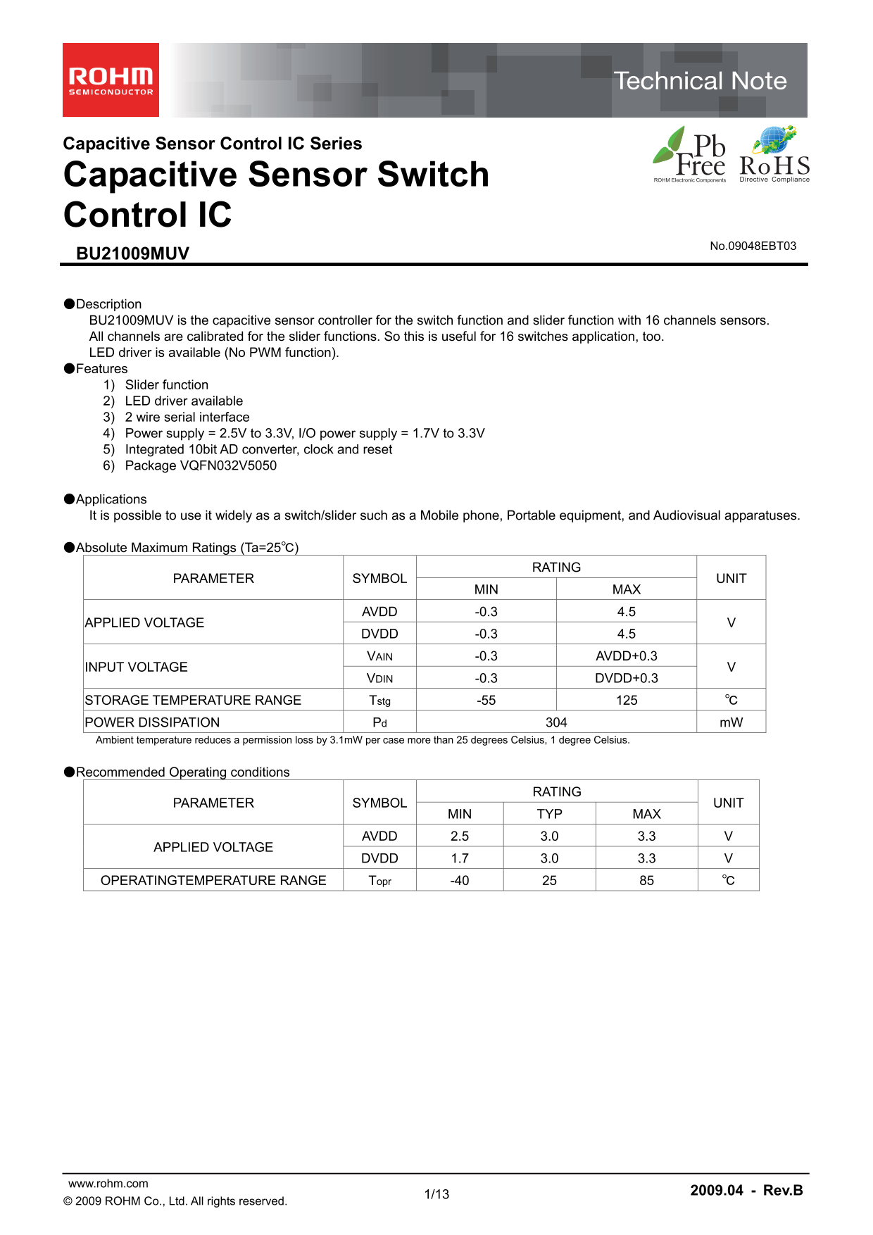
Page 1 Text Content
Capacitive Sensor Control IC Series
Capacitive Sensor Switch Control IC
No.09048EBT03
BU21009MUV
●Description BU21009MUV is the capacitive sensor controller for the switch function and slider function with 16 channels sensors. All channels are calibrated for the slider functions. So this is useful for 16 switches application, too. LED driver is available (No PWM function). ●Features 1) Slider function 2) LED driver available 3) 2 wire serial interface 4) Power supply = 2.5V to 3.3V, I/O power supply = 1.7V to 3.3V 5) Integrated 10bit AD converter, clock and reset 6) Package VQFN032V5050
●Applications It is possible to use it widely as a switch/slider such as a Mobile phone, Portable equipment, and Audiovisual apparatuses.
●Absolute Maximum Ratings (Ta=25℃)
RATING
PARAMETER SYMBOL UNIT
MIN MAX
AVDD -0.3 4.5
APPLIED VOLTAGE
DVDD -0.3 4.5 VAIN -0.3 AVDD+0.3
INPUT VOLTAGE
VDIN -0.3 DVDD+0.3
STORAGE TEMPERATURE RANGE Tstg -55 125 ℃ POWER DISSIPATION Pd 304 m W Ambient temperature reduces a permission loss by 3.1m W per case more than 25 degrees Celsius, 1 degree Celsius.
●Recommended Operating conditions
RATING
PARAMETER SYMBOL UNIT
MIN TYP MAX
AVDD 2.5 3.0 3.3 V
APPLIED VOLTAGE
DVDD 1.7 3.0 3.3 V
OPERATINGTEMPERATURE RANGE Topr -40 25 85 ℃
www.rohm.com 2009.04 - Rev.B
© 2009 ROHM Co., Ltd. All rights reserved.
Page Summary Contents For ROHM BU21009MUV Data Manual
Manual Details
| Brand | ROHM |
|---|---|
| Pages | 14 |
| File Size | 314.69 KB |
| Published | July 16, 2026 |
Enter the captcha to get the download link:

Frequently Asked Questions
How does the chip manage sensor drift and accuracy?
The data correction and CV translate circuit implements auto-calibration to manage drift caused by temperature, process variation, voltage variation, and aging effects.
What are the operating voltage requirements for the controller?
AVDD must be between 2.5V and 3.3V, while DVDD should range from 1.7V to 3.3V when operating normally.
How is a sensor touch event reported to an external system?
The power management block monitors usage; if a sensor is touched, the device automatically wakes up and drives the dedicated INT pin for alerting.