ROHM BH6453GUL Data Manual
Summary
These advanced motor driver ICs are designed for high-precision auto-focus systems utilizing Voice Coil motors. Offering ultra-small, specialized functional lens control, this family provides Constant-Current and Constant-Voltage driving capabilities via multiple H-bridge configurations. This technical manual serves as a comprehensive guide for electrical engineers and product designers developing professional electronic equipment (e.g., A/V devices, communication tools) requiring reliable, low-power optical operation. It details the absolute maximum ratings, operational parameters, and core specifications of models like BD6883GUL and BH6453GUL.
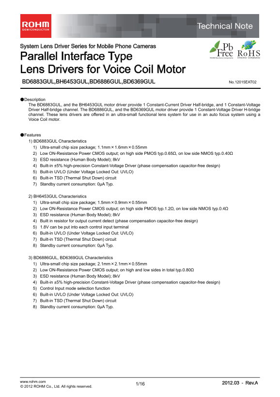
Page 1 Text Content
System Lens Driver Series for Mobile Phone Cameras
Parallel Interface Type Lens Drivers for Voice Coil Motor
BD6883GUL,BH6453GUL,BD6886GUL,BD6369GUL No.12015EAT02
●Description The BD6883GUL, and the BH6453GUL motor driver provide 1 Constant-Current Driver Half-bridge, and 1 Constant-Voltage Driver Half-bridge channel. The BD6886GUL, and the BD6369GUL motor driver provide 1 Constant-Voltage Driver H-bridge channel. These lens drivers are offered in an ultra-small functional lens system for use in an auto focus system using a Voice Coil motor.
●Features 1) BD6883GUL Characteristics 1) Ultra-small chip size package; 1.1mm×1.6mm×0.55mm 2) Low ON-Resistance Power CMOS output; on high side PMOS typ.0.65Ω, on low side NMOS typ.0.40Ω 3) ESD resistance (Human Body Model); 8k V 4) Built-in ±5% high-precision Constant-Voltage Driver (phase compensation capacitor-free design) 5) Built-in UVLO (Under Voltage Locked Out: UVLO) 6) Built-in TSD (Thermal Shut Down) circuit 7) Standby current consumption: 0μA Typ.
2) BH6453GUL Characteristics 1) Ultra-small chip size package; 1.5mm×0.9mm×0.55mm 2) Low ON-Resistance Power CMOS output; on high side PMOS typ.1.2Ω, on low side NMOS typ.0.4Ω 3) ESD resistance (Human Body Model); 8k V 4) Built in resistor for output current detect (phase compensation capacitor-free design) 5) 1.8V can be put into each control input terminal 6) Built-in UVLO (Under Voltage Locked Out: UVLO) 7) Built-in TSD (Thermal Shut Down) circuit 8) Standby current consumption: 0μA Typ.
3) BD6886GUL, BD6369GUL Characteristics 1) Ultra-small chip size package; 2.1mm×2.1mm×0.55mm 2) Low ON-Resistance Power CMOS output; on high and low sides in total typ.0.80Ω 3) ESD resistance (Human Body Model); 8k V 4) Built-in ±5% high-precision Constant-Voltage Driver (phase compensation capacitor-free design) 5) Control Input mode selection function 6) Built-in UVLO (Under Voltage Locked Out: UVLO) 7) Built-in TSD (Thermal Shut Down) circuit 8) Standby current consumption: 0μA Typ.
www.rohm.com 2012.03 - Rev.A
© 2012 ROHM Co., Ltd. All rights reserved.
Page Summary Contents For ROHM BH6453GUL Data Manual
Manual Details
| Brand | ROHM |
|---|---|
| Pages | 17 |
| File Size | 349.68 KB |
| Published | May 31, 2026 |
Enter the captcha to get the download link:

Frequently Asked Questions
What types of output channels are available across these motor drivers?
Some models offer a Constant-Current Driver Half-bridge and Constant-Voltage Driver Half-bridge, while others provide a Constant-Voltage Driver H-bridge channel.
Are there built-in safety or protection circuits?
Yes, the drivers include built-in UVLO (Under Voltage Locked Out) and TSD (Thermal Shut Down) circuits for enhanced safety.
Can these drivers be used in critically reliable systems like medical instruments?
No, they are not intended for equipment where failure could result in a direct threat to human life or create risk of injury.
What is the typical standby current consumption?
For most models (BD6883GUL, BH6453GUL, BD6886GUL, BD6369GUL), the standby current consumption is 0μA Typ.