ROHM ES6U3 Data Manual
Summary
This integrated semiconductor device combines a MOSFET and a Schottky barrier diode (ES6U3) optimized for high-speed switching applications. The comprehensive manual provides detailed technical specifications, including absolute maximum ratings, electrical characteristics, and multiple performance curves necessary for accurate circuit design. This product is essential for engineers developing general electronic equipment, such as sophisticated audio/visual gear, communication devices, or other switching power systems requiring reliable, low on-resistance performance in critical circuits.
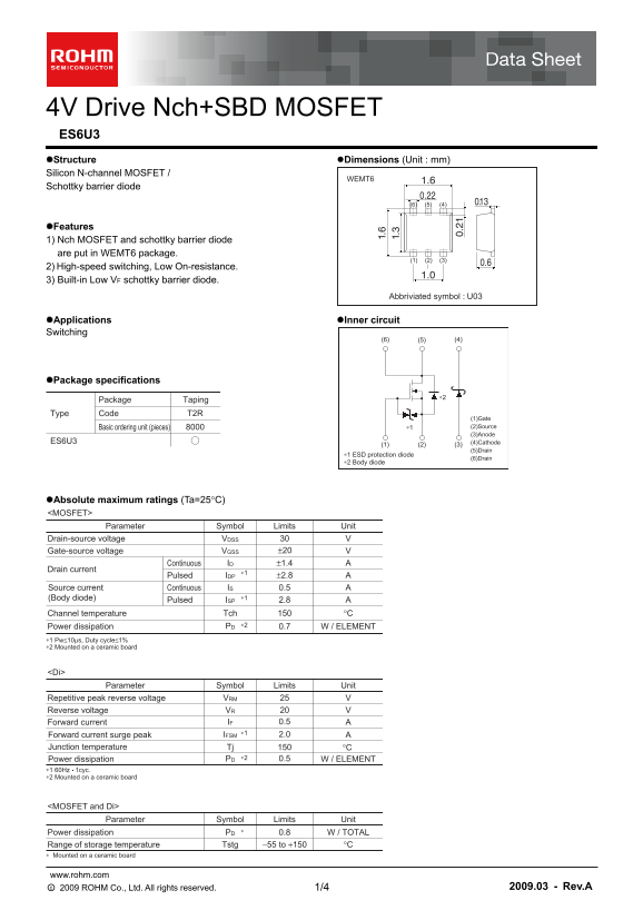
Page 1 Text Content
4V Drive Nch+SBD MOSFET ES6U3 Structure Dimensions (Unit : mm) Silicon N-channel MOSFET /
WEMT6
Schottky barrier diode
Features 1) Nch MOSFET and schottky barrier diode are put in WEMT6 package.
2) High-speed switching, Low On-resistance. 3) Built-in Low VF schottky barrier diode.
Abbriviated symbol : U03
Applications Inner circuit Switching
Package specifications
Package Taping
Type Code T2R
(1)Gate Basic ordering unit (pieces) ∗1 (2)Source (3)Anode
ES6U3 (4)Cathode
(5)Drain
∗1 ESD protection diode
(6)Drain
∗2 Body diode
Absolute maximum ratings (Ta=25°C) <MOSFET>
Parameter Symbol Limits Unit
Drain-source voltage VVDSS
Gate-source voltage ±20 VVGSS Continuous ±1.4 AID
Drain current
Pulsed ±2.8 AIDP Source current Continuous 0.5 AIS
(Body diode) ∗1
Pulsed 2.8 AISP
°CTch Channel temperature
∗2PDPower dissipation W / ELEMENT0.7
∗1 Pw≤10µs, Duty cycle≤1% ∗2 Mounted on a ceramic board
Parameter Symbol Limits Unit
Repetitive peak reverse voltage VVRM Reverse voltage VVR
Forward current 0.5 AIF
Forward current surge peak AIFSM Junction temperature Tj °C
∗2Power dissipation 0.5 W / ELEMENTPD
∗1 60Hz 1cyc. ∗2 Mounted on a ceramic board
<MOSFET and Di>
Parameter Symbol Limits Unit
Power dissipation 0.8 W / TOTALPD
Range of storage temperature −55 to +150 °CTstg
∗ Mounted on a ceramic board
www.rohm.com ○c 2009 ROHM Co., Ltd. All rights reserved. 2009.03 - Rev.A 1/4
Page Summary Contents For ROHM ES6U3 Data Manual
Manual Details
| Brand | ROHM |
|---|---|
| Pages | 5 |
| File Size | 203.88 KB |
| Published | June 05, 2026 |
Enter the captcha to get the download link:

Frequently Asked Questions
Can I use this MOSFET in life-critical applications like medical or aerospace equipment?
No, it is not designed for systems requiring an extremely high level of reliability; consultation is required for such special purposes.
What is the maximum Drain-Source Voltage (VDSS) rating for this component?
The absolute maximum drain-source voltage ($V_{DSS}$) allowed is 30 V.
Does the package include built-in protection or monitoring diodes?
Yes, it features both a body diode and an incorporated Schottky barrier diode ($D_i$) providing ESD protection.
What safety protocols must be implemented when integrating this product into custom equipment?
You must implement safety measures such as derating, redundancy, or fire-safe designs to prevent potential physical injury or damage.