ROHM BD6735FV BD6736FV Data Manual
Summary
These ROHM motor drivers are essential components engineered for precise operation in digital still and Single-Lens Reflex (SLR) cameras with interchangeable lenses. Providing robust H-bridge motor control, they deliver high voltage resistance and large current output for reliable lens focusing and zooming mechanisms. This technical guide details the full electrical characteristics of both models, covering critical integration features such as low ON-Resistance power MOS outputs, built-in thermal protection (TSD), and UVLO circuits, making it indispensable for camera system manufacturers needing dependable motor drive solutions.
Page 1 Text Content
System Lens Driver Series for Digital Still Cameras / Single-lens Reflex Cameras
1 to 2ch Lens Drivers for Single-Lens Reflex Cameras
No.09014EAT03
BD6735FV, BD6736FV
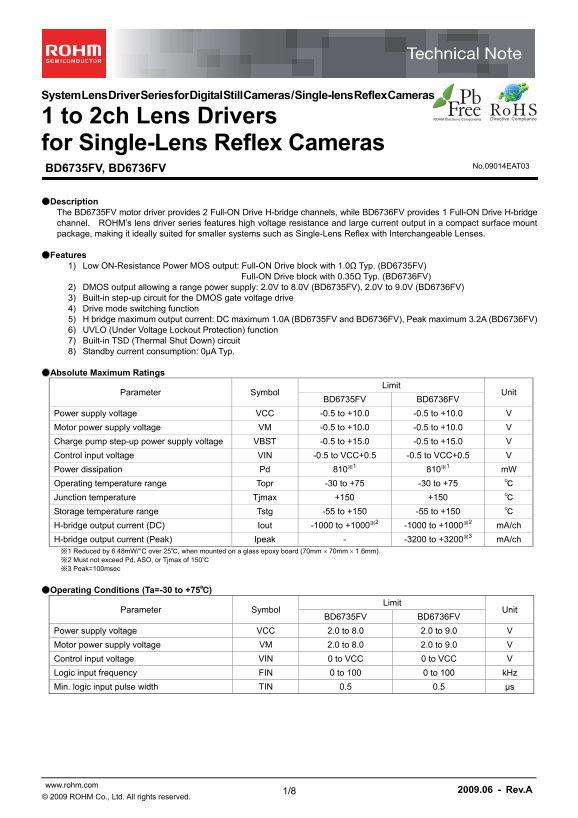
●Description The BD6735FV motor driver provides 2 Full-ON Drive H-bridge channels, while BD6736FV provides 1 Full-ON Drive H-bridge channel. ROHM’s lens driver series features high voltage resistance and large current output in a compact surface mount package, making it ideally suited for smaller systems such as Single-Lens Reflex with Interchangeable Lenses.
●Features 1) Low ON-Resistance Power MOS output: Full-ON Drive block with 1.0Ω Typ. (BD6735FV)
Full-ON Drive block with 0.35Ω Typ. (BD6736FV)
2) DMOS output allowing a range power supply: 2.0V to 8.0V (BD6735FV), 2.0V to 9.0V (BD6736FV) 3) Built-in step-up circuit for the DMOS gate voltage drive 4) Drive mode switching function 5) H bridge maximum output current: DC maximum 1.0A (BD6735FV and BD6736FV), Peak maximum 3.2A (BD6736FV) 6) UVLO (Under Voltage Lockout Protection) function 7) Built-in TSD (Thermal Shut Down) circuit 8) Standby current consumption: 0μA Typ.
●Absolute Maximum Ratings
Limit
Parameter Symbol Unit
BD6735FV BD6736FV
Power supply voltage VCC -0.5 to +10.0 -0.5 to +10.0 V Motor power supply voltage VM -0.5 to +10.0 -0.5 to +10.0 V Charge pump step-up power supply voltage VBST -0.5 to +15.0 -0.5 to +15.0 V Control input voltage VIN -0.5 to VCC+0.5 -0.5 to VCC+0.5 V Power dissipation Pd 810※1 810※1 m W Operating temperature range Topr -30 to +75 -30 to +75 ℃ Junction temperature Tjmax +150 +150 ℃ Storage temperature range Tstg -55 to +150 -55 to +150 ℃ H-bridge output current (DC) Iout -1000 to +1000※2 -1000 to +1000※2 m A/ch H-bridge output current (Peak) Ipeak - -3200 to +3200※3 m A/ch ※1 Reduced by 6.48m W/°C over 25℃, when mounted on a glass epoxy board (70mm 70mm 1.6mm). ※2 Must not exceed Pd, ASO, or Tjmax of 150℃ ※3 Peak=100msec
●Operating Conditions (Ta=-30 to +75℃)
Limit
Parameter Symbol Unit
BD6735FV BD6736FV
Power supply voltage VCC 2.0 to 8.0 2.0 to 9.0 V Motor power supply voltage VM 2.0 to 8.0 2.0 to 9.0 V Control input voltage VIN 0 to VCC 0 to VCC V Logic input frequency FIN 0 to 100 0 to 100 k Hz Min. logic input pulse width TIN 0.5 0.5 μs
www.rohm.com 2009.06 - Rev.A
© 2009 ROHM Co., Ltd. All rights reserved.
Page Summary Contents For ROHM BD6735FV BD6736FV Data Manual
Manual Details
| Brand | ROHM |
|---|---|
| Pages | 9 |
| File Size | 355.06 KB |
| Published | June 04, 2026 |
Enter the captcha to get the download link:

Frequently Asked Questions
What is the primary application for the BD6735FV and BD6736FV drivers?
They are lens motor drivers designed for Single-Lens Reflex Cameras, featuring H-bridge channels in a compact surface mount package.
How durable are these chips regarding voltage fluctuations?
They include UVLO (Under Voltage Lockout Protection) and a built-in TSD (Thermal Shut Down) circuit for operational safety.
Are these products suitable for extremely reliable or life-support devices?
No, they must not be used in systems requiring an extremely high level of reliability, such as medical instruments or nuclear-reactor controllers.