RICOH RP504x SERIES Data Manual (1) Service Manual
Summary
This low supply current DC/DC converter provides highly efficient, regulated voltage step-down power for demanding applications like portable communication devices, cameras, and battery systems. The RP504x series utilizes synchronous rectification and advanced features, including soft start, UVLO, and latch protection. Whether you require fixed PWM operation or seamless automatic switching between PWM and high-efficiency VFM mode, this versatile component can be easily integrated using minimal external components. The documentation provides detailed selection guides to help designers choose the optimal package and control method for their specific power requirements.
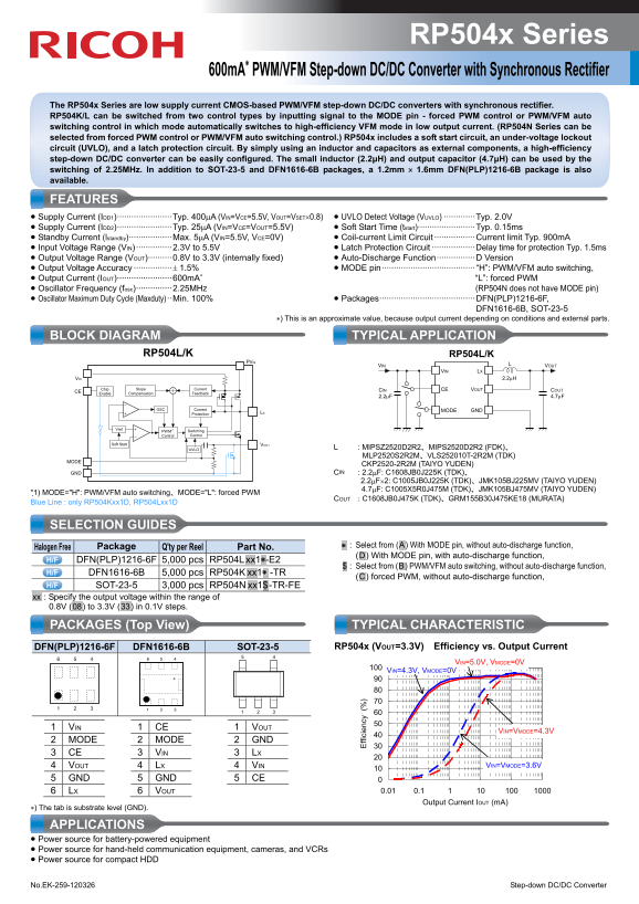
Page 1 Text Content
RP504x Series
600m A∗ PWM/VFM Step-down DC/DC Converter with Synchronous Rectifier
The RP504x Series are low supply current CMOS-based PWM/VFM step-down DC/DC converters with synchronous rectifier. RP504K/L can be switched from two control types by inputting signal to the MODE pin - forced PWM control or PWM/VFM auto switching control in which mode automatically switches to high-efficiency VFM mode in low output current. (RP504N Series can be selected from forced PWM control or PWM/VFM auto switching control.) RP504x includes a soft start circuit, an under-voltage lockout circuit (UVLO), and a latch protection circuit. By simply using an inductor and capacitors as external components, a high-efficiency step-down DC/DC converter can be easily configured. The small inductor (2.2μH) and output capacitor (4.7μH) can be used by the switching of 2.25MHz. In addition to SOT-23-5 and DFN1616-6B packages, a 1.2mm × 1.6mm DFN(PLP)1216-6B package is also available.
FEATURES • Supply Current (IDD1)·······················Typ. 400μA (VIN=VCE=5.5V, VOUT=VSET×0.8) • UVLO Detect Voltage (VUVLO) ·············Typ. 2.0V • Supply Current (IDD2)·······················Typ. 25μA (VIN=VCE=VOUT=5.5V) • Soft Start Time (tstart)························Typ. 0.15ms • Standby Current (Istandby)··················Max. 5μA (VIN=5.5V, VCE=0V) • Coil-current Limit Circuit ·················Current limit Typ. 900m A • Input Voltage Range (VIN) ···············2.3V to 5.5V • Latch Protection Circuit ··················Delay time for protection Typ. 1.5ms • Output Voltage Range (VOUT)··········0.8V to 3.3V (internally fixed) • Auto-Discharge Function················D Version • Output Voltage Accuracy ················± 1.5% • MODE pin······································· “H”: PWM/VFM auto switching, • Output Current (IOUT)·······················600m A∗ “L”: forced PWM • Oscillator Frequency (fosc)···············2.25MHz (RP504N does not have MODE pin) • Oscillator Maximum Duty Cycle (Maxduty) ··Min. 100% • Packages········································DFN(PLP)1216-6F,
DFN1616-6B, SOT-23-5
∗) This is an approximate value, because output current depending on conditions and external parts.
BLOCK DIAGRAM TYPICAL APPLICATION
RP504L/K RP504L/K
ffi ci en cy VIN VOUT
VIN LX
VIN 2.2μH
Chip Slope Current CIN CE VOUT COUT
CE Enable Compensation Feedback
OSC Current GND MODE
Protection LX
Vref PWM∗1 Switching
Control Control
Soft Start VOUT
UVLO L : MIPSZ2520D2R2、MIPS2520D2R2 (FDK)、
MLP2520S2R2M、VLS252010T-2R2M (TDK)
CKP2520-2R2M (TAIYO YUDEN)
GND CIN : 2.2μF: C1608JB0J225K (TDK)、
2.2μF×2: C1005JB0J225K (TDK)、JMK105BJ225MV (TAIYO YUDEN) 4.7μF: C1005X5R0J475M (TDK)、JMK105BJ475MV (TAIYO YUDEN)
*1) MODE="H": PWM/VFM auto switching、MODE="L": forced PWM
COUT : C1608JB0J475K (TDK)、GRM155B30J475KE18 (MURATA)
Blue Line : only RP504Kxx1D, RP504Lxx1D
SELECTION GUIDES
.∗ . : Select from (.A.) With MODE pin, without auto-discharge function,
Halogen Free Package Q'ty per Reel Part No.
(.D.) With MODE pin, with auto-discharge function,
DFN(PLP)1216-6F 5,000 pcs RP504L .xx1∗-E2
$ : Select from (.B.) PWM/VFM auto switching, without auto-discharge function,
DFN1616-6B 5,000 pcs RP504K .xx1∗ -TR
(.C.) forced PWM, without auto-discharge function,
SOT-23-5 3,000 pcs RP504N .xx1$ -TR-FE .xx. : Specify the output voltage within the range of 0.8V (.08.) to 3.3V (.33.) in 0.1V steps.
PACKAGES (Top View) TYPICAL CHARACTERISTIC
DFN(PLP)1216-6F DFN1616-6B SOT-23-5 RP504x (VOUT=3.3V) Efficiency vs. Output Current
VIN=5.0V, VMODE=0V
VIN=4.3V, VMODE=0V
1 VIN 1 CE 1 VOUT
VIN=VMODE=4.3V
2 MODE 2 MODE 2 GND 3 CE 3 VIN 3 LX
4 VOUT 4 LX 4 VIN VIN=VMODE=3.6V
5 GND 5 GND 5 CE
6 LX 6 VOUT 0.01 0.1
Output Current IOUT (m A)
∗) The tab is substrate level (GND).
APPLICATIONS • Power source for battery-powered equipment • Power source for hand-held communication equipment, cameras, and VCRs • Power source for compact HDD
No.EK-259-120326 Step-down DC/DC Converter
Page Summary Contents For RICOH RP504x SERIES Data Manual (1) Service Manual
Manual Details
| Brand | Ricoh |
|---|---|
| Pages | 2 |
| File Size | 361.40 KB |
| Published | June 01, 2026 |
Enter the captcha to get the download link:

Frequently Asked Questions
How can I switch between PWM and VFM control modes?
For the RP504K/L series, you can switch modes by applying a signal to the MODE pin for forced PWM (MODE="L") or automatic switching (MODE="H").
What is the recommended external setup for the DC/DC converter?
A high-efficiency converter can be configured using only an inductor and capacitors as external components, such as a 2.2μH inductor and a 4.7μF capacitor.
What protection features does the RP504x series include?
It includes soft start, under-voltage lockout (UVLO), and a latch protection circuit for reliable operation.