# A B C D E F G H I J K L M N O P Q R S T U V W X Y Z

RICOH RP107x SERIES Owner's Manual User Guide

Summary

This advanced CMOS LDO regulator provides highly efficient 200mA power conversion for sensitive electronics. Featuring ultra-low standby currents and an innovative capacitor-less design, it operates efficiently across a wide input range (Min. 1.4V) while supporting portable, high-density designs. The manual offers comprehensive technical details on electrical characteristics, package selection guides (WLCSP, DFN), pin configurations, and ideal operating conditions. It is essential for designers of battery-powered equipment, portable communication devices, and modern household appliances requiring stable, low-noise voltage regulation.
📄 Preview PAGE OF 26

Page 1 Text Content

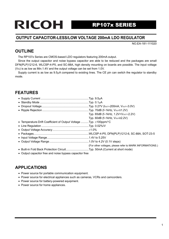
RP107x SERIES

OUTPUT CAPACITOR-LESS/LOW VOLTAGE 200m A LDO REGULATOR

NO.EA-181-111020

OUTLINE The RP107x Series are CMOS-based LDO regulators featuring 200m A output. Since the output capacitor and noise bypass capacitor are able to be reduced and the packages are small DFN(PLP)1212-6, WLCSP-4-P5, and SC-88A, high density mounting on boards are possible. The input voltage (VIN) is as low as Min.1.4V and the output voltage can be set from 1.0V. Supply current is as low as 9.5μA compared to existing lines. The CE pin can switch the regulator to standby mode.

FEATURES • Supply Current .............................................................Typ. 9.5μA • Standby Mode ..............................................................Typ. 0.1μA • Dropout Voltage............................................................Typ. 0.27V (IOUT=200m A, VOUT=3.0V) • Ripple Rejection ...........................................................Typ. 70d B (f=1k Hz, VOUT≤1.2V) Typ. 65d B (f=1k Hz, 1.2V<VOUT<2.2V) Typ. 60d B (f=1k Hz, VOUT≥2.2V) • Temperature-Drift Coefficient of Output Voltage ..........Typ. ±100ppm/°C • Line Regulation ............................................................Typ. 0.02%/V • Output Voltage Accuracy..............................................±1.0% • Packages......................................................................WLCSP-4-P5, DFN(PLP)1212-6, SC-88A, SOT-23-5 • Input Voltage Range.....................................................1.4V to 5.25V • Output Voltage Range..................................................1.0V to 4.2V (0.1V steps) (For other voltages, please refer to MARK INFORMATIONS.) • Built-in Fold Back Protection Circuit.............................Typ. 50m A (Current at short mode) • Output capacitor free and noise bypass capacitor free

APPLICATIONS • Power source for portable communication equipment. • Power source for electrical appliances such as cameras, VCRs and camcorders. • Power source for battery-powered equipment. • Power source for home appliances.

Page Summary Contents For RICOH RP107x SERIES Owner's Manual User Guide

Page 1 RP107x SERIES OUTPUT CAPACITOR-LESS/LOW VOLTAGE 200m A LDO REGULATOR NO.EA-181-111020 OUTLINE The RP107x Series are CMOS-based LDO regulators featuring 200m A output. Since the output capacitor and no...
Page 2 RP107x BLOCK DIAGRAMS RP107xxxx B RP107xxxx D VDD VOUT VDD VOUT Vref Vref Current Limit Current Limit CE GND CE GND SELECTION GUIDE The output voltage, auto discharge function, package, and the taping...
Page 3 RP107x PIN CONFIGURATIONS • WLCSP-4-P5 • DFN(PLP)1212-6 • SC-88A • SOT-23-5 Silicon Side Bump Side Top View Bottom View (mark side) (mark side) PIN DESCRIPTIONS • WLCSP-4-P5 Pin No Symbol Pin Descript...
Page 4 RP107x ABSOLUTE MAXIMUM RATINGS Symbol Item Rating Unit VIN Input Voltage 6.0 V VCE Input Voltage (CE Pin) −0.3 to 6.0 V VOUT Output Voltage −0.3 to VIN+0.3 V IOUT Output Current 400 m A Power Dissipa...
Page 5 RP107x ELECTRICAL CHARACTERISTICS • RP107xxxx B/D VIN=Set VOUT+1.0V, IOUT=1m A, CIN=COUT=0.1μF, unless otherwise noted. The specification in is checked and guaranteed by design engineering at −40°C≤To...
Page 6 RP107x TYPICAL APPLICATION VDD VOUT VOUT CIN RP107x COUT∗ Series CE GND TECHNICAL NOTES When using these ICs, consider the following points: Phase Compensation∗) In these ICs, phase compensation is ma...
Page 7 RP107x PCB Layout Make VDD and GND lines sufficient. If their impedance is high, noise pickup or unstable operation may result. Connect a capacitor CIN with a capacitance value as much as 0.1μF or mor...
Page 8 RP107x Pulse VDD VOUT Generator RP107x COUT IOUT P.G. Series CE GND Test Circuit for Ripple Rejection VDD VOUT VOUT C1 RP107x COUT Series CE GND IOUTa IOUTb Test Circuit for Load Transient Response
Page 9 lta tp lta lta tp lta RP107x ■ Constant Slope Circuits The RP107x Series is equipped with a constant slope circuit as a soft-start circuit, which allows the output voltage to start up gradually when t...
Page 10 tp lt ag tp lt ag tp lt ag RP107x TYPICAL CHARACTERISTICS 1) Output Voltage vs. Output Current (CIN=0.1μF, Topt=25°C) RP107x101x RP107x151x 1.2 1.6 Vin=1.4V 2.0V 0.4 Vin=2.0 Vin=1.8V Vin=2.5V Vin=2.0V...
Page 11 pp ly rr [u pp ly rr [u tp lt ag RP107x RP107x281x RP107x421x Iout=1m A Iout=1m A Iout=30m A Iout=30m A Iout=50m A Iout=50m A Input Voltage [V] Input Voltage [V] 3) Supply Current vs. Input Voltage (C...
Page 12 ut pu t V ol ta ge [V ut pu t V ol ta ge [V up pl ur re nt u A RP107x 4) Output Voltage vs. Temperature (CIN=0.1μF, IOUT=1m A) RP107x101x RP107x151x Vin=2.0V Vin=2.5V RP107x101x RP107x151x Temperature...
Page 13 ro po lt ag ro po lt ag RP107x up pl ur re nt u A RP107x281x RP107x421x Vin=3.8V Vin=5.25V RP107x281x RP107x421x Temperature [°C] Temperature [°C] ro po lt ag ro po lt ag up pl ur re nt u A 6) Dropout...
Page 14 ro po lt ag ro po lt ag ro po lt ag RP107x RP107x201x RP107x301x Output Current [m A] Output Current [m A] RP107x421x ro po lt ag ro po lt ag Output Current [m A] 7) Dropout Voltage vs. Set Output Vol...
Page 15 In pu lt ag RP107x ro po lt ag ro po lt ag RP107x RP107x RP107xxx1x Iout=50m A Iout=100m A RP107xxx1x Output Voltage [V] Output Voltage [V] RP107x ro po lt ag RP107xxx1x Iout=200m A Output Voltage [V]...
Page 16 ip pl je ti d B ip pl je ti d B RP107x ip pl je ti d B 9) Ripple Rejection vs. Frequency (CIN=none, Topt=25°C) RP107x101x RP107x151x Cout=none Vin=2.0V+0.2Vp-p Vin=2.5V+0.2Vp-p Cout=none R107x101x RP1...
Page 17 ip pl je ti d B RP107x ip pl je ti d B ip pl je ti d B RP107x281x RP107x421x Cout=0.1u FVin=3.8V+0.2Vp-p Cout=0.1u FVin=5.2V+0.2Vp-p RP107x281x RP107x421x Frequency [k Hz] Frequency [k Hz] 10) Ripple ...
Page 18 ut pu t V ol ta ge (V ut pu t V ol ta ge V) ut pu t V ol ta ge RP107x 11) Input Transient Response (CIN=none, IOUT=30m A, tr=tf=5μs, Topt=25°C) RP107x101x RP107x101x Cout=none Vin:2V⇔3V RP107x101x Vin...
Page 19 ut pu t V ol ta (V ut pu t V ol ta ge (V ut pu t V ol ta ge V) RP107x RP107x421x RP107x421x Vin:4.5V⇔5.5V Cout=none Vin:4.5V⇔5.5V Cout=Ceramic 0.1µF RP107x421x RP107x421x Input Voltage Input Voltage O...
Page 20 tp ut lt ag ut pu t V ol ta ge (V ut pu t V ol ta ge V) RP107x RP107x281x RP107x281x RP107x281x RP107x281x Tr=Tf: 2µs Tr=Tf: 0.5µs Iout : 5m A⇔50m A Iout : 50m A⇔100m A 3.2 Input Voltage 3.2 Output Cu...
Page 21 tp ol ta ge ut pu lt ge ut pu lt ge RP107x RP107x281x RP107x421x Vin=3.8V Cout=none Vin=5.2V Cout=none RP107x281x RP107x421x -0.7 -5 -0.7 -4 pu ol ta ge pu lt ag [V pu lt ge Time [us] Time [us] ut pu ...
Page 22 ut pu lt ag [V tp ol ta ge ut pu lt ge RP107x 14) Turn Off Speed with CE pin (D Version) (CIN=0.1μF, Topt=25°C) RP107x101D RP107x151D Cout=none Vin=2.0V Cout=none Vin=2.5V RP107x101x RP107x151x pu lt ...
Page 23 In pu t V ol ta ge E( In pu t V ol ta ge E( ut pu lt ag [V ut pu t V ol ta ge T( V) ut pu t V ol ta ge T( V) RP107x RP107x281D RP107x421D Cout=1u FVin=3.8V RP107x281x Cout=1u FVin=5.2V RP107x421x In r...
Page 24 In pu t V ol ta ge E( In pu t V ol ta ge E( V) In pu t V ol ta ge E( ut pu t V ol ta ge T( V) ut pu t V ol ta ge T( ut pu t V ol ta ge T( V) RP107x RP107x281x RP107x281x VIN =3 .8 VIN =3 .8 T=C ra ic1...
Page 25 (Ω RP107x ESR vs. Output Current When using these ICs, consider the following points: The relations between IOUT (Output Current) and ESR of an output capacitor are shown below. The conditions when th...
Page 26 1. The products and the product specifications described in this document are subject to change or discontinuation of production without notice for reasons such as improvement. Therefore, before decid...

Manual Details

Brand Ricoh
Pages 26
File Size 877.71 KB
Published June 01, 2026
90 views

Enter the captcha to get the download link:

captcha

Frequently Asked Questions

What is the primary function and key specifications of this LDO regulator?

It's a CMOS-based LDO with 200mA output, supporting input voltages from 1.4V to 5.25V, and setting outputs from 1.0V to 4.2V.

How can I reduce power consumption or manage the device when not in use?

The supply current is very low (Typ. 9.5μA), and the CE pin allows switching the regulator into a standby mode with even lower current (Typ. 0.1μA).

Does this regulator require large external capacitors?

No, it features output capacitor-less and noise bypass capacitor-free operation.

What is the guaranteed operating temperature range for the device?

The operational temperature range for the RP107x series is from -40 to 85 °C.