RICOH R5106N SERIES Microprocessor Supervisory Circuit with Inhibit pin Data Manual User Guide
Summary
This advanced CMOS supervisory circuit provides critical system protection by combining precise voltage monitoring with a watchdog timer. Whether detecting supply dips or processor lockups, it generates a reliable reset signal to maintain equipment stability. This manual serves as your comprehensive guide, detailing technical specifications, pin configurations, delay time adjustment methods, and product selection options for seamless integration into microprocessor-based systems. Ideal for engineers designing industrial controls, embedded devices, and stable electronic equipment requiring robust operational safety features.
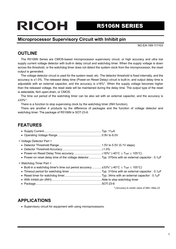
Page 1 Text Content
R5106N SERIES
Microprocessor Supervisory Circuit with Inhibit pin
NO.EA-169-111103
OUTLINE The R5106N Series are CMOS-based microprocessor supervisory circuit, or high accuracy and ultra low supply current voltage detector with built-in delay circuit and watchdog timer. When the supply voltage is down across the threshold, or the watchdog timer does not detect the system clock from the microprocessor, the reset output is generated. The voltage detector circuit is used for the system reset, etc. The detector threshold is fixed internally, and the accuracy is ±1.0%. The released delay time (Power-on Reset Delay) circuit is built-in, and output delay time is adjustable with an external capacitor, and the accuracy is ±16%*. When the supply voltage becomes higher than the released voltage, the reset state will be maintained during the delay time. The output type of the reset is selectable, Nch open-drain, or CMOS. The time out period of the watchdog timer can be also set with an external capacitor, and the accuracy is ±33%*. There is a function to stop supervising clock by the watchdog timer (INH function). There are another 4 products by the difference of packages and the function of voltage detector and watchdog timer. The package of R5106N is SOT-23-6.
FEATURES • Supply Current...................................................................... Typ. 11μA • Operating Voltage Range 0.9V to 6.0V < Voltage Detector Part > • Detector Threshold Range.................................................... 1.5V to 5.5V (0.1V steps) • Detector Threshold Accuracy................................................±1.0% • Power-on Reset Delay Time accuracy ±16%* (-40°C Topt 105°C) • Power-on reset delay time of the voltage detector Typ. 370ms with an external capacitor : 0.1μF < Watchdog Timer Part > • Built-in a watchdog timer's time out period accuracy ±33%* (-40°C Topt 105°C) • Timeout period for watchdog timer Typ. 310ms with an external capacitor : 0.1μF • Reset timer for watchdog timer............................................. Typ. 34ms with an external capacitor : 0.1μF • With Inhibit pin (INH)............................................................. Able to stop watchdog timer • Package................................................................................ SOT-23-6
*) Accuracy to center value of (Min.+Max.)/2
APPLICATIONS • Supervisory circuit for equipment with using microprocessors.
Page Summary Contents For RICOH R5106N SERIES Microprocessor Supervisory Circuit with Inhibit pin Data Manual User Guide
Manual Details
| Brand | Ricoh |
|---|---|
| Pages | 15 |
| File Size | 275.18 KB |
| Published | June 04, 2026 |
Enter the captcha to get the download link:

Frequently Asked Questions
What signal does the R5106N output when a fault is detected?
The RESETB pin outputs a low signal ("L") if either the supply voltage drops or the watchdog timer fails to detect system clock activity.
How can I adjust the detector threshold and delay periods?
The threshold must be selected by specifying the part number (1.5V to 5.5V), while reset/watchdog delays are adjusted using external capacitors on the CT pin.
Is it possible to temporarily disable the watchdog functionality?
Yes, the INH (Inhibit) pin can be used to halt and stop supervising the watchdog timer's function.