RICOH R5107G SERIES Microprocessor Supervisory Circuit with Manual Reset Data Sheet User Manual
Summary
The R5107G Series is a high-accuracy CMOS microprocessor supervisory circuit designed to ensure system integrity. This comprehensive manual details its dual functionality: reliable supply voltage detection and integrated watchdog timing. The device provides robust system reset capability—generating an output signal when the voltage drops below threshold or when the CPU stops pulsing. Featuring adjustable delay times, selectable output types (CMOS or open-drain), and built-in inhibit/manual reset functions, it is essential for engineers designing microprocessor systems requiring fail-safe power monitoring and reliable operational supervision.
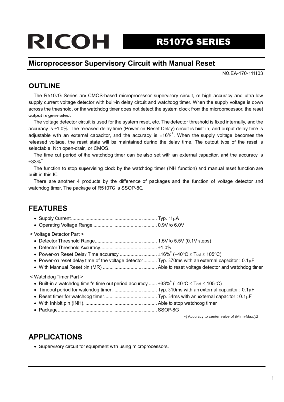
Page 1 Text Content
R5107G SERIES
Microprocessor Supervisory Circuit with Manual Reset
NO.EA-170-111103
OUTLINE The R5107G Series are CMOS-based microprocessor supervisory circuit, or high accuracy and ultra low supply current voltage detector with built-in delay circuit and watchdog timer. When the supply voltage is down across the threshold, or the watchdog timer does not detect the system clock from the microprocessor, the reset output is generated. The voltage detector circuit is used for the system reset, etc. The detector threshold is fixed internally, and the accuracy is ±1.0%. The released delay time (Power-on Reset Delay) circuit is built-in, and output delay time is adjustable with an external capacitor, and the accuracy is ±16%∗. When the supply voltage becomes the released voltage, the reset state will be maintained during the delay time. The output type of the reset is selectable, Nch open-drain, or CMOS. The time out period of the watchdog timer can be also set with an external capacitor, and the accuracy is ±33%∗. The function to stop supervising clock by the watchdog timer (INH function) and manual reset function are built in this IC. There are another 4 products by the difference of packages and the function of voltage detector and watchdog timer. The package of R5107G is SSOP-8G.
FEATURES • Supply Current................................................................. Typ. 11μA • Operating Voltage Range 0.9V to 6.0V < Voltage Detector Part > • Detector Threshold Range............................................... 1.5V to 5.5V (0.1V steps) • Detector Threshold Accuracy........................................... ±1.0% • Power-on Reset Delay Time accuracy ±16%∗ (−40°C ≤ Topt ≤ 105°C) • Power-on reset delay time of the voltage detector Typ. 370ms with an external capacitor : 0.1μF • With Mannual Reset pin (MR) Able to reset voltage detector and watchdog timer < Watchdog Timer Part > • Built-in a watchdog timer's time out period accuracy ±33%∗ (−40°C ≤ Topt ≤ 105°C) • Timeout period for watchdog timer Typ. 310ms with an external capacitor : 0.1μF • Reset timer for watchdog timer........................................ Typ. 34ms with an external capacitor : 0.1μF • With Inhibit pin (INH)........................................................ Able to stop watchdog timer • Package........................................................................... SSOP-8G
∗) Accuracy to center value of (Min.+Max.)/2
APPLICATIONS • Supervisory circuit for equipment with using microprocessors.
Page Summary Contents For RICOH R5107G SERIES Microprocessor Supervisory Circuit with Manual Reset Data Sheet User Manual
Manual Details
| Brand | Ricoh |
|---|---|
| Pages | 18 |
| File Size | 283.37 KB |
| Published | June 02, 2026 |
Enter the captcha to get the download link:

Frequently Asked Questions
How do I set the duration for the voltage detector's power-on reset delay?
The output delay time is adjustable using an external capacitor connected to the CD pin.
What are the selectable settings for the circuit's operating voltage range?
The specified operating voltage range is 0.9V to 6.0V.
Is there a way to manually force a system reset?
Yes, using the Manual Reset Pin (MR) allows you to reset both the voltage detector and the watchdog timer.
How can I temporarily prevent the watchdog timer from resetting the system?
You must use the Inhibit pin (INH) to stop the watchdog timer function.