# A B C D E F G H I J K L M N O P Q R S T U V W X Y Z

RICOH R1283x SERIES 2ch DC-DC Converter for CCD & OLED Quick User Guide & Data Sheet

Summary

This dual-channel DC/DC converter is engineered to provide stable power for demanding CCD and OLED display backlights. It features an independently boosting channel (CH1) providing positive voltage up to 20V and an inverting channel (CH2) generating negative output. The manual details system setup, multiple operating configurations, advanced protections (over current/short circuit), multiple frequencies, and package options. Ideal for engineers designing portable electronic devices requiring reliable dual-polar power sources for specialized display applications.
📄 Preview PAGE OF 25

Page 1 Text Content

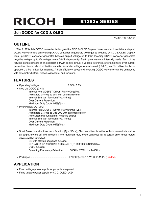
R1283x SERIES

2ch DC/DC for CCD & OLED

NO.EA-157-120404

OUTLINE The R1283x 2ch DC/DC converter is designed for CCD & OLED Display power source. It contains a step up DC/DC converter and an inverting DC/DC converter to generate two required voltages by CCD & OLED Display. Step up DC/DC converter generates boosted output voltage up to 20V. Inverting DC/DC converter generates negative voltage up to VIN voltage minus 20V independently. Start up sequence is internally made. Each of the R1283x series consists of an oscillator, a PWM control circuit, a voltage reference, error amplifiers, over current protection circuits, short protection circuits, an under voltage lockout circuit (UVLO), an Nch driver for boost operation, a Pch driver for inverting. A high efficiency boost and inverting DC/DC converter can be composed with external inductors, diodes, capacitors, and resistors.

FEATURES • Operating Voltage 2.5V to 5.5V • Step Up DC/DC (CH1)

Internal Nch MOSFET Driver (RON=400mΩTyp.) Adjustable VOUT Up to 20V with external resistor Internal Soft start function (Typ. 4.5ms) Over Current Protection Maximum Duty Cycle: 91%(Typ.)

• Inverting DC/DC (CH2)

Internal Pch MOSFET Driver (RON=400mΩ Typ.) Adjustable VOUT Up to Vdd-20V with external resistor Auto Discharge function for negative output Internal Soft start function (Typ. 4.5ms) Over Current Protection Maximum Duty Cycle: 91%(Typ.)

• Short Protection with timer latch function (Typ. 50ms); Short condition for either or both two outputs makes all output drivers off and latches./ If the maximum duty cycle continues for a certain time, these output drivers will be turned off.

CE with start up sequence function CH1→CH2 (R1283K001x) / CH2→CH1(R1283K002x) Selectable UVLO function Operating Frequency Selection ..........300k Hz / 700k Hz / 1400k Hz

• Packages DFN(PLP)2730-12, WLCSP-11-P2 (Limited)

APPLICATION • Fixed voltage power supply for portable equipment • Fixed voltage power supply for CCD, OLED, LCD

Page Summary Contents For RICOH R1283x SERIES 2ch DC-DC Converter for CCD & OLED Quick User Guide & Data Sheet

Page 1 R1283x SERIES 2ch DC/DC for CCD & OLED NO.EA-157-120404 OUTLINE The R1283x 2ch DC/DC converter is designed for CCD & OLED Display power source. It contains a step up DC/DC converter and an inv...
Page 2 BLOCK DIAGRAM Timer Current Limit PWM Control Maxduty VREF Vref Discharge Control VOUTN PWM Control Sequence CE PGND Control
Page 3 SELECTION GUIDE The start-up sequence, oscillator frequency, and the package for the ICs can be selected at the user’s request. Product Name Package Quantity per Reel Pb Free Halogen Free R1283Z00x∗-E...
Page 4 PIN CONFIGURATIONS • WLCSP-11-P2 • DFN(PLP)2730-12 Bottom View Top View Bottom View Top View D C B A ABC D PIN DESCRIPTIONS • WLCSP-11-P2 (Limited) Pin No Symbol Pin Description A1 PGND Power GND pin ...
Page 5 ABSOLUTE MAXIMUM RATINGS (GND/PGND=0V) Symbol Item Rating Unit VCC VCC / PVCC pin Voltage 6.5 V VDTC VFB1 pin Voltage −0.3 to VCC+0.3 V VFB VFB2 pin Voltage −0.7(∗1) to VCC+0.3 V VCE CE pin Voltage −0...
Page 6 ELECTRICAL CHARACTERISTICS • R1283x Topt=25°C Symbol Item Conditions Min. Typ. Max. Unit. VCC Operating Input Voltage 2.5 5.5 V VCC=5.5V, FREQ=300k Hz 2.0 m A VCC=5.5V, FREQ=700k Hz 4.0 m A ICC1 VCC C...
Page 7 TYPICAL APPLICATION VOUT1 VCC R3 PGND R2 VOUTN VOUT2 EN CE GND R4 • Step-up DC/DC converter output voltage setting The output voltage VOUT1 of the step-up DC/DC converter is controlled with maintainin...
Page 8 • Start up Sequence (R1283x001x) When CE level turns from "L" to "H" level, the softstart of CH1 starts the operation. After detecting output voltage of CH1(VOUT1) as the nominal l...
Page 9 Fzero ~ 1/(2×π×R2×C5) (CH1) Fzero ~ 1/(2×π×R5×C6) (CH2) Set the cut-off frequency of the Zero close to the cut off frequency of the pole by L and C. • To reduce the noise of Feedback voltage If the no...
Page 10 There are two operation modes for the PWM control step-up switching regulator, that is the continuous mode and the discontinuous mode. When the LX Tr. is on, the voltage for the inductor L will be VIN...
Page 11 Operation of Inverting DC/DC Converter and Output Current <Basic Circuit> Lx Tr Diode IOUT VOUT IL1 IL2 Inductor <Current through L> Discontinuous Mode Continuous Mode ILxmax IL IL ILxmax ILxmin ILxmi...
Page 12 VIN × ton / L = VOUT × toff / L ...........................................................................................Formula10 In the continuous mode, the duty cycle will be: DUTY = ton / (ton +...
Page 13 TYPICAL CHARACTERISTICS TYPCAL CHARACTERISTICS 1) Output Voltage VS. Output Current Topt=25°C Topt=25°C VIN=2.8V 4.7 -4.3 VIN=3.6V VIN=4.2V VIN=2.8V VIN=3.6V VIN=4.2V [V [V [V IOUT1 [m A] IOUT2 [m A] ...
Page 14 Topt=25°C Topt=25°C VIN=2.8V VIN=3.6V 12.2 VIN=4.2V -7.4 VIN=5.0V VIN=2.8V VIN=3.6V VIN=4.2V VIN=5.0V IOUT1 [m A] IOUT2 [m A] Topt=25°C Topt=25°C VIN=2.8V VIN=3.6V VIN=4.2V VIN=2.8V VIN=3.6V VIN=4.2V ...
Page 15 Ef fic ie nc Ef fic ie nc Ef fic ie nc 2) Efficiency VS. Output Current Topt=25 , VOUT1=4.6V Topt=25℃ , VOUT2=-4.4V VOUT2=-4.4V , IOUT2=0m A VOUT1=4.6V , IOUT1=0m A VIN=2.8 [V] VIN=2.8 [V] VIN=3.6 [V]...
Page 16 Ef fic ie nc Ef fic ie nc Ef fic ie nc Topt=25°C , VOUT1=12V Topt=25°C, VOUT2=-7.5V VOUT2=-7.5V , IOUT2=0m A VOUT1=12V , IOUT1=0m A VIN=2.8 [V] VIN=2.8 [V] VIN=3.6 [V] VIN=3.6 [V] VIN=4.2 [V] VIN=4.2 ...
Page 17 [V FB [V R1283x perature 4) CE "H" Input Voltage VS. Temparature 3) CE "L" Input Voltage VS. Temparature R1283x00xx R1283x00xx VIN=5.5V VIN=2.5V Topt [°C] Topt [°C] FB [V LO [V 5) ...
Page 18 FO [k z] IL IM LX [A LX [Ω 9) LX1 ON Resistance VS. Temparature erature e 10) LX2 ON Resistance VS. Temparature R1283x00xx R1283x00xx FO Topt [°C] [k z] Topt [°C] LX [Ω IL IM LX [m 11) LX1 Limit Curre...
Page 19 FO [k z] ax du ty R1283x ax du ty Topt [°C] ax du ty ax du ty 14) Maxduty1 VS. Temparature perature Topt [°C] Topt [°C] 15) Maxduty2 VS. Temparature perature Topt [°C] Topt [°C]
Page 20 TD LY [m s] ax du ty TS [m s] Topt [°C] Topt [°C] IV TN [m ax du ty TS [m s] 16) CH1 Soft-start Time VS. Temparature Temperature e 17) CH2 Soft-start Time VS. Temparature R1283x00xx R1283x00xx Topt [°...
Page 21 ut pu t V ol ta ge [V R1283x ut pu t V ol ta ge [V ut pu t V ol ta ge [V 20) Startup Response Topt=25°C , VIN=3.6V Topt=25°C , VIN=3.6V VOUT1=12V , VOUT2=-7.5V VOUT1=12V , VOUT2=-7.5V VOUT1 VOUT1 -3 V...
Page 22 ut pu t V ol ta ge [V ut pu t V ol ta ge [V ut pu t V ol ta ge [V 22) Load Transient Response Topt=25°C , VIN=3.6V Topt=25°C , VIN=3.6V ut pu t C ur re nt [m -7.7 ut pu t C ur re nt [m ut pu t C ur re...
Page 23 APPLIED CIRCUIT 1) Application with outputting power supply (+12V/-7.5V) for CCD from Li battery L1 SBD VOUT1= 12V VOUTN PVCC SBD LX2 VOUT2= -7.5V 10u F EN L2 1kΩ GND 12kΩ L1 L2 C5 C6 Inductor VLF3010...
Page 24 3) Application with output disconnect and discharge. LX1 VOUT1 VOUTN PVCC SBD LX2 VOUT2 EN CE
Page 25 1. The products and the product specifications described in this document are subject to change or discontinuation of production without notice for reasons such as improvement. Therefore, before decid...

Manual Details

Brand Ricoh
Pages 25
File Size 526.60 KB
Published June 04, 2026
43 views

Enter the captcha to get the download link:

captcha

Frequently Asked Questions

What is the basic function of the R1283x converter?

It provides power for CCD and OLED displays by generating two required voltages using a step-up and an inverting DC/DC converter.

How can I adjust the output voltage (VOUT)?

The VOUT for both channels is adjustable up to 20V (for CH1) or Vdd-20V (for CH2) by connecting an external resistor.

What types of protection features are built-in?

It includes Over Current Protection, Short Protection with a timer latch function, and Under Voltage Lockout (UVLO).

Does the device start up automatically?

Yes, the startup sequence is internally generated. You can also select the sequence: CH1→CH2 or CH2→CH1.