Page 1
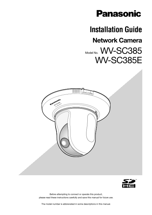
Installation Guide Network Camera Model No. WV-SC385 WV-SC385E C38 WV-S Before attempting to connect or operate this product, please read these instructions carefully and save this manual for future u...
Page 2
We declare under our sole responsibility that the product to which this Wij verklaren als enige aansprakelijke, dat het product waarop deze declaration relates is in conformity with the standards or o...
Page 3
Contents Important safety instructions ............................................................................................................................................. Limitation of liabi...
Page 4
Important safety instructions 1) Read these instructions. 2) Keep these instructions. 3) Heed all warnings. 4) Follow all instructions. 5) Do not use this apparatus near water. 6) Clean only with dry ...
Page 5
Limitation of liability THIS PUBLICATION IS PROVIDED "AS IS" WITHOUT WARRANTY OF ANY KIND, EITHER EXPRESS OR IMPLIED, INCLUDING BUT NOT LIMITED TO, THE IMPLIED WARRANTIES OF MERCHANTABILITY,...
Page 6
Preface The network camera WV-SC385 is designed to operate using a PC on a network (10BASE-T/100BASE-TX). By connecting to a network (LAN) or the Internet, images and audio from the camera can be moni...
Page 7
About the user manuals There are 2 sets of operating instructions for the WV-SC385 (NTSC model), WV-SC385E (PAL model) as follows. • Installation Guide: Explains how to install and connect devices, as...
Page 8
Trademarks and registered trademarks • Microsoft, Windows, Windows Vista, Internet Explorer, Active X and Direct X are either registered trademarks or trade- marks of Microsoft Corporation in the Unit...
Page 9
Precautions Refer installation work to the dealer. The exclusively designed mount bracket shall be Installation work requires technique and experiences. used. Failure to observe this may cause fire, e...
Page 10
Do not touch the transparent part (over the lens) • When using an unformatted SDHC/SD memory card, with your bare hands. format it using this product. Recorded data on the The dirty part causes deteri...
Page 11
AVC Patent Portfolio License This product is licensed under the AVC Patent Portfolio License for the personal and noncommercial use of a con- sumer to (i) encode video in compliance with the AVC Stand...
Page 12
Precautions for installation No responsibility will be taken by our company with Procure fixing screws separately. respect to consequeces resulting from the use, The screws that secure this product ar...
Page 13
Major operating controls Camera mount bracket (accessory) Safety wire (fixed with the mount bracket) WV-SC385 Decorative cover (accessory) LO CK Camera Front view Transparent part (over the lens) WV-S...
Page 14
Rear view INITIAL SET button Cable guide Access indicator (blinking at accessing) Audio output connector 10BASE-T/ 100BASE-TX Link indicator ACTLINK POWERINITIAL MONITOR OUTAUDIO OUTMIC/LINE INEXT I/O...
Page 15
Installations/Connections Caution: • FOR UL LISTED MODEL(S), ONLY CONNECT 12 V DC CLASS 2 POWER SUPPLY. The following are descriptions of how to install the camera. The camera can be installed on a ce...
Page 16
Wire through a hole in the ceiling 2- /3 2" Step 1 Step 3 Fix the camera mount bracket (accessory) with four Insert the SDHC/SD memory card into the SDHC/SD optional fixing screws (M4 or M6, opti...
Page 17
Specification of cable (wire): AWG #22 - #28, Single core, twisted Important: Strip range • Connect/disconnect the audio cables and turn on the power of the camera after turning off the power of the E...
Page 18
Center of the Step 8 camera mount bracket Connect the cables to the network connector and the power inlet. Important: • When the power of the camera is turned on, the cam- era will start panning and t...
Page 19
• 12 V DC power supply terminal Step 9 q Loosen the screw of the power cord plug (accessory). After completing the cable connections, attach the deco- w Connect the cable of the 12 V DC power supply* ...
Page 20
Wire without making a hole in the ceiling Step 1 Install the camera by following step 1 and steps 3 - 8 of the "Wire through a hole in the ceiling" section (☞ pages 16 - 18). It is unnecessa...
Page 21
Place the camera upside-down on a desktop without fixing Use it as a simple desktop device at meetings and on other occasions. Place the camera on a level place not subject to vibrations. Ensure that ...
Page 22
Connection example When connecting with a PC directly Speaker with amplifier (option) LAN cable Microphone (option) (category 5 or better, cross, STP*) To AC outlet <Required cable> LAN cable (c...
Page 23
Detach the camera The camera is fixed on the camera mount bracket using the fixing screw. Remove the camera by following the instructions below. The following is an example of installation on the ceil...
Page 24
Insert/remove an SDHC/SD memory card How to insert an SDHC/SD memory card Important: • Before inserting the SDHC/SD memory card, turn off the power of the camera first. • When inserting an SDHC/SD mem...
Page 25
How to remove the SDHC/SD memory card Important: • Before removing the SDHC/SD memory card, select "Not use" for "SD memory card" on the [SD memory card] tab of "Basic" o...
Page 26
Configure the network settings Install the software Before installing the software, refer to the readme file on the provided CD-ROM first. Software included on the provided CD-ROM • Panasonic IP setti...
Page 27
Step 1 Step 3 Start the Panasonic IP setting software. Complete each network setup item and click the [Save] button. Step 2 Click the [Network Settings] button after selecting the MAC address/IP addre...
Page 28
Troubleshooting Before asking for repairs, check the symptoms with the following table. Contact your dealer if a problem cannot be solved even after checking and trying the solution in the table or a ...
Page 29
Reference Symptom Cause/solution pages • UPn PTM error has occurred since the power is not supplied to the router. Turn on the power of the router. Wait until the connections are established. • An err...
Page 30
About the live indicator The live indicator will light or blink as follows depending on the camera status. Operation status Indicator status When the power is turned on Before the network Blinks orang...
Page 31
Specifications • Basic Power source: 12 V DC, Po E (IEEE802.3af compliant) Power consumption: 12 V DC*: Approx. 1 A, Po E: Approx. 12 W (Class 0 device) * FOR UL LISTED MODEL(S), ONLY CONNECT 12 V DC ...
Page 32
Camera title on screen: On/Off Up to 20 characters (alphanumeric characters, marks) Character size: Large/Middle/Small Video motion detection (VMD alarm): On/Off, 4 areas available Image hold: On/Off ...
Page 33
Bandwidth control: Unlimited/ 64kbps/ 128kbps/ 256kbps/ 384kbps/ 512kbps/ 768kbps/ 1024kbps/ 2048kbps/ 4096kbps/ 8192kbps Protocol: IPv6: TCP/IP, UDP/IP, HTTP, HTTPS, RTP, FTP, SMTP, DNS, NTP, SNMP, D...
Page 34
Standard accessories Installation Guide (this document) ....................................1 pc. Warranty card (NTSC model only) ....................................1 pc. CD-ROM* .......................
Page 35
Information for Users on Collection and Disposal of Old Equipment and used Batteries These symbols on the products, packaging, and/or accompanying documents mean that used electrical and electronic pr...
Page 36
For U.S. and Canada: For Europe and other countries: Panasonic System Networks Company of America, Panasonic Corporation Unit of Panasonic Corporation of North America http://panasonic.net www.panason...