Panasonic WV-CW244F, WV- CW244S CCTV Camera User Manual
Summary
Operating instructions for Panasonic WV-CW244S/WV-CW244F color CCTV cameras designed for surveillance applications. Includes comprehensive precaut ions covering NEC conformity for qualified service personnel installation, class 2 power source requirement (12V DC or 24V AC), proper ceiling/wall mounting with sufficient strength, operating temperature range -10°C to +50°C (14°F to 122°F) with humidity below 90%, and avoidance of direct sunlight or bright objects to prevent blooming/smear. Details
Page 1 Text Content
PRECAUTIONS WV-CW244S
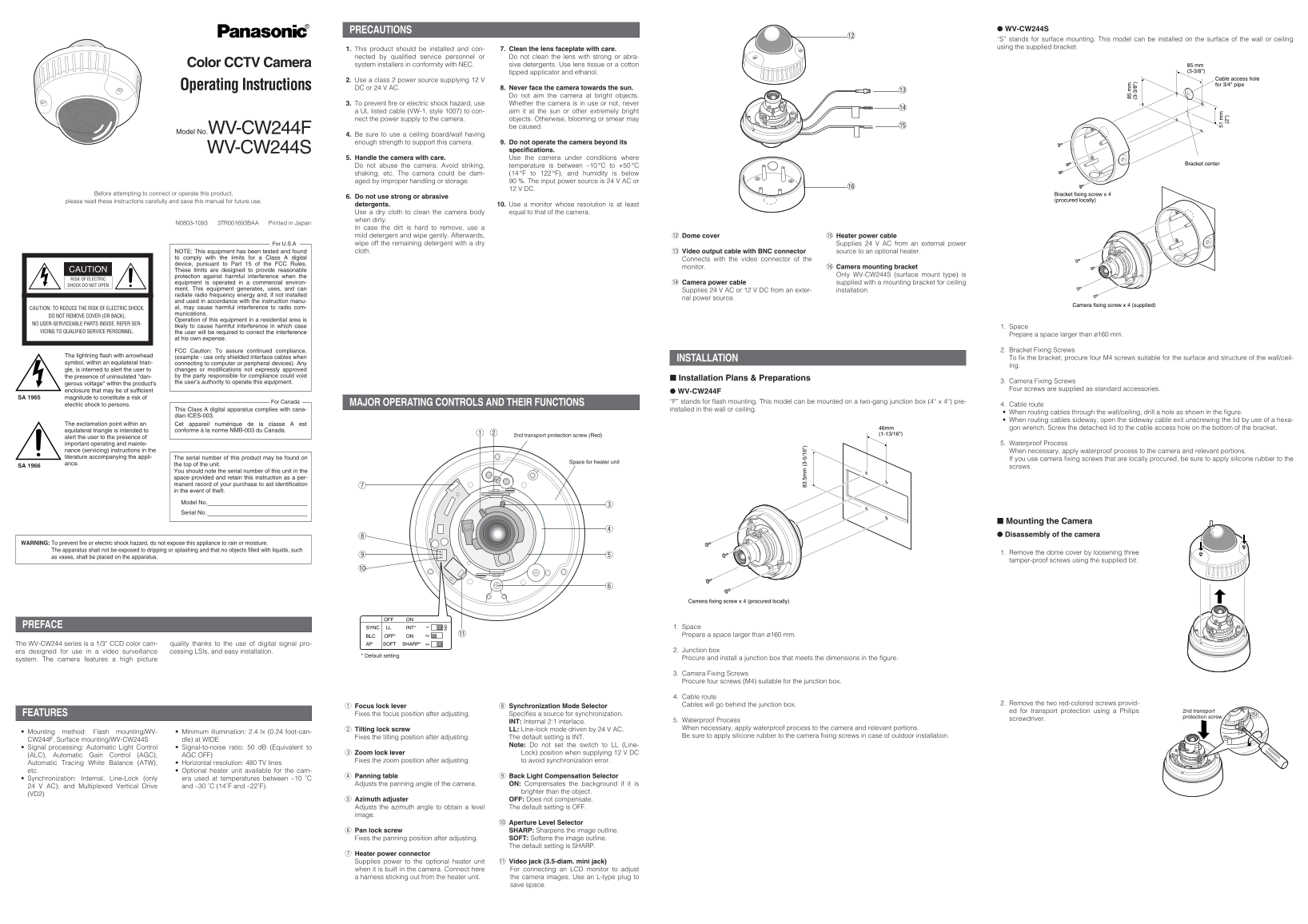
“S” stands for surface mounting. This model can be installed on the surface of the wall or ceiling using the supplied bracket.
1. This product should be installed and con- 7. Clean the lens faceplate with care. nected by qualified service personnel or Do not clean the lens with strong or abra- Color CCTV Camera system installers in conformity with NEC. sive detergents. Use lens tissue or a cotton 85 mm
tipped applicator and ethanol. (3-3/8")
Cable access hole
2. Use a class 2 power source supplying 12 V
for 3/4" pipe
Operating Instructions DC or 24 V AC. 8. Never face the camera towards the sun.
Do not aim the camera at bright objects.
3. To prevent fire or electric shock hazard, use Whether the camera is in use or not, never
a UL listed cable (VW-1, style 1007) to con- aim it at the sun or other extremely bright nect the power supply to the camera. objects. Otherwise, blooming or smear may
be caused. !5
Model No.WV-CW244F
4. Be sure to use a ceiling board/wall having
enough strength to support this camera. 9. Do not operate the camera beyond its WV-CW244S specifications. 5. Handle the camera with care. Use the camera under conditions where
Bracket center
Do not abuse the camera. Avoid striking, temperature is between –10 °C to +50 °C shaking, etc. The camera could be dam- (14 °F to 122 °F), and humidity is below aged by improper handling or storage. %. The input power source is 24 V AC or
12 V DC.
Before attempting to connect or operate this product, Bracket fixing screw x 4
6. Do not use strong or abrasive
please read these instructions carefully and save this manual for future use. (procured locally)
detergents. 10. Use a monitor whose resolution is at least
Use a dry cloth to clean the camera body equal to that of the camera. when dirty.
N0803-1093 3TR001693BAA Printed in Japan
In case the dirt is hard to remove, use a mild detergent and wipe gently. Afterwards, !2 Dome cover !5 Heater power cable For U.S.A wipe off the remaining detergent with a dry Supplies 24 V AC from an external power NOTE: This equipment has been tested and found cloth. !3 Video output cable with BNC connector source to an optional heater.
to comply with the limits for a Class A digital
Connects with the video connector of the
device, pursuant to Part 15 of the FCC Rules.
monitor. !6 Camera mounting bracket
CAUTION These limits are designed to provide reasonable
protection against harmful interference when the Only WV-CW244S (surface mount type) is
RISK OF ELECTRIC
equipment is operated in a commercial environ- !4 Camera power cable supplied with a mounting bracket for ceiling
SHOCK DO NOT OPEN
ment. This equipment generates, uses, and can
Supplies 24 V AC or 12 V DC from an exter- installation.
radiate radio frequency energy and, if not installed
nal power source.
and used in accordance with the instruction manu-
Camera fixing screw x 4 (supplied)
CAUTION: TO REDUCE THE RISK OF ELECTRIC SHOCK, al, may cause harmful interference to radio com- munications.
DO NOT REMOVE COVER (OR BACK).
Operation of this equipment in a residential area is
NO USER-SERVICEABLE PARTS INSIDE. REFER SER-
likely to cause harmful interference in which case 1. Space
VICING TO QUALIFIED SERVICE PERSONNEL. the user will be required to correct the interference
Prepare a space larger than ø160 mm.
at his own expense.
FCC Caution: To assure continued compliance, 2. Bracket Fixing Screws
The lightning flash with arrowhead (example - use only shielded interface cables when
INSTALLATION To fix the bracket, procure four M4 screws suitable for the surface and structure of the wall/ceil-
symbol, within an equilateral trian- connecting to computer or peripheral devices). Any
gle, is interned to alert the user to changes or modifications not expressly approved the presence of uninsulated "dan- by the party responsible for compliance could void
Installation Plans & Preparations
the user’s authority to operate this equipment. 3. Camera Fixing Screws
gerous voltage" within the product's
enclosure that may be of sufficient Four screws are supplied as standard accessories.
WV-CW244F
SA 1965 magnitude to constitute a risk of
For Canada “F” stands for flash mounting. This model can be mounted on a two-gang junction box (4“ x 4“) pre-
electric shock to persons. MAJOR OPERATING CONTROLS AND THEIR FUNCTIONS 4. Cable route
This Class A digital apparatus complies with cana- installed in the wall or ceiling.
When routing cables through the wall/ceiling, drill a hole as shown in the figure.
dian ICES-003.
When routing cables sideway, open the sideway cable exit unscrewing the lid by use of a hexa-
The exclamation point within an Cet appareil numérique de la classe A est
46mm gon wrench. Screw the detached lid to the cable access hole on the bottom of the bracket.
equilateral triangle is intended to conforme à la norme NMB-003 du Canada.
2nd transport protection screw (Red) (1-13/16")
alert the user to the presence of
important operating and mainte- 5. Waterproof Process
nance (servicing) instructions in the When necessary, apply waterproof process to the camera and relevant portions. literature accompanying the appli- The serial number of this product may be found on
If you use camera fixing screws that are locally procured, be sure to apply silicone rubber to the
Space for heater unit
ance. the top of the unit.
SA 1966 screws.
You should note the serial number of this unit in the space provided and retain this instruction as a per- manent record of your purchase to aid identification in the event of theft.
Model No. Serial No.
Mounting the Camera Disassembly of the camera
WARNING: To prevent fire or electric shock hazard, do not expose this appliance to rain or moisture.
The apparatus shall not be exposed to dripping or splashing and that no objects filled with liquids, such
1. Remove the dome cover by loosening three
as vases, shall be placed on the apparatus.
tamper-proof screws using the supplied bit.
Camera fixing screw x 4 (procured locally)
OFF ON
PREFACE LLSYNC INT* 1. Space
OFF*BLC ON !1 Prepare a space larger than ø160 mm.
The WV-CW244 series is a 1/3” CCD color cam- quality thanks to the use of digital signal pro- SOFTAP SHARP*
era designed for use in a video surveillance cessing LSIs, and easy installation. 2. Junction box
* Default setting
system. The camera features a high picture Procure and install a junction box that meets the dimensions in the figure.
3. Camera Fixing Screws Procure four screws (M4) suitable for the junction box.
4. Cable route
Cables will go behind the junction box. 2. Remove the two red-colored screws provid-
Focus lock lever Synchronization Mode Selector
ed for transport protection using a Philips 2nd transport
FEATURES Fixes the focus position after adjusting. Specifies a source for synchronization.
protection screw
5. Waterproof Process screwdriver.
INT: Internal 2:1 interlace.
Tilting lock screw LL: Line-lock mode driven by 24 V AC. When necessary, apply waterproof process to the camera and relevant portions.
Mounting method: Flash mounting/WV- Minimum illumination: 2.4 lx (0.24 foot-can-
Fixes the tilting position after adjusting. The default setting is INT. Be sure to apply silicone rubber to the camera fixing screws in case of outdoor installation.
CW244F, Surface mounting/WV-CW244S dle) at WIDE
Note: Do not set the switch to LL (Line-
Signal processing: Automatic Light Control Signal-to-noise ratio: 50 d B (Equivalent to
Zoom lock lever Lock) position when supplying 12 V DC
(ALC), Automatic Gain Control (AGC), AGC OFF)
Fixes the zoom position after adjusting. to avoid synchronization error.
Automatic Tracing White Balance (ATW), Horizontal resolution: 480 TV lines etc. Optional heater unit available for the cam-
Panning table Back Light Compensation Selector
Synchronization: Internal, Line-Lock (only era used at temperatures between –10 ˚C
Adjusts the panning angle of the camera. ON: Compensates the background if it is
24 V AC), and Multiplexed Vertical Drive and –30 ˚C (14˚F and –22˚F).
brighter than the object.
(VD2)
Azimuth adjuster OFF: Does not compensate.
Adjusts the azimuth angle to obtain a level The default setting is OFF.
image.
!0 Aperture Level Selector
Pan lock screw SHARP: Sharpens the image outline.
Fixes the panning position after adjusting. SOFT: Softens the image outline. The default setting is SHARP.
Heater power connector
Supplies power to the optional heater unit !1 Video jack (3.5-diam. mini jack) N1 when it is built in the camera. Connect here For connecting an LCD monitor to adjust a harness sticking out from the heater unit. the camera images. Use an L-type plug to save space.
Page Summary Contents For Panasonic WV-CW244F, WV- CW244S CCTV Camera User Manual
Manual Details
| Brand | Panasonic |
|---|---|
| Pages | 2 |
| File Size | 732.72 KB |
| Published | June 19, 2026 |
Enter the captcha to get the download link:

Frequently Asked Questions
What is the recommended temperature range for operation?
The camera's operating temperature range is between –10°C to +50°C (14°F to 122°F).
How should I clean the lens faceplate?
Use lens tissue or a cotton tipped applicator with ethanol or a mild detergent. For hard dirt, wipe gently with a mild detergent and dry completely.
What must I use when routing cables through walls or ceilings?
Drill a hole as shown in the figure, and apply waterproof material like silicone clay (rubber) to seal gaps, screws, and holes.
Is there any restriction on aiming the camera?
Never aim the camera towards the sun, bright objects, or operate it beyond its specifications to prevent blooming or smear.