Page 1
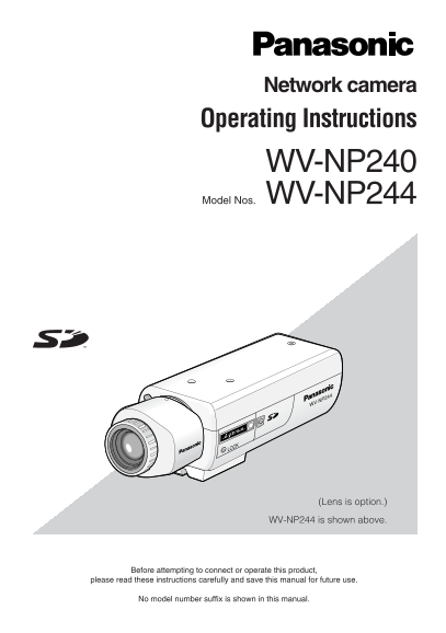
Network camera Operating Instructions WV-NP240 Model Nos. WV-NP244 WV-NP244 (Lens is option.) WV-NP244 is shown above. Before attempting to connect or operate this product, please read these instructi...
Page 2
We declare under our sole responsibility that the product to Vi erklærer os eneansvarlige for, at dette produkt, som denne which this declaration relates is in conformity with the standards deklaratio...
Page 3
Important Safety Instructions 1) Read these instructions. 2) Keep these instructions. 3) Heed all warnings. 4) Follow all instructions. 5) Do not use this apparatus near water. 6) Clean only with dry ...
Page 4
Limitation of Liability THIS PUBLICATION IS PROVIDED "AS IS" THIS PUBLICATION COULD INCLUDE WITHOUT WARRANTY OF ANY KIND, TECHNICAL INACCURACIES OR TYPO- EITHER EXPRESS OR IMPLIED, INCLUDING...
Page 5
Preface The network camera WV-NP240/WV-NP244 is designed to operate using a PC on a network (10BASE-T/100BASE-TX) to monitor images. By connecting to a network (LAN) or the Internet, images and audio ...
Page 6
About these Operating Instructions There are 2 sets of operating instructions for the WV-NP240/WV-NP244 as follows. Operating Instructions (book, these operating instructions) Network Operating Instru...
Page 7
CONTENTS Important Safety Instructions ..................................................................................................... Limitation of Liability ......................................
Page 8
Precautions Refer to all work related to the installation the restart just as when the power is turned of this product to qualified service person- on. nel or system installer. Cleaning the camera bod...
Page 9
Otherwise, the camera may not work Radio interference properly or performance deterioration When the camera is used near TV/radio may be caused. antenna, strong electric field or magnetic Images saved...
Page 10
Major Operating Controls and Their Functions Model number is shown here. Tripod mount base Focus fixing screw (LOCK) Back focus adjusting ring* Microphone ALC lens connector SD card memory slot Lens (...
Page 11
<REAR> WV-NP244WV-NP240 10BASE-T/ 10BASE-T/ MONITOR OUT LINK 100BASE-TX ACT MONITOR OUT LINK 100BASE-TX ACT INITIAL SET INITIAL SET EXT I/O SD EXT I/O SD 1 2 3 4 CARD 1 2 3 4 CARD POWER POWER 22...
Page 12
Lens Mounting Mount the lens by rotating it clockwise slowly. Then, connect the lens cable to the ALC lens connector of the camera. Back focus adjusting ring* Zoom lock knob Focus ring ALC lens connec...
Page 13
How to use a vari-focal lens The following are descriptions of how to use a 2x vari-focal lens. Method of adjustment may be different depending on the lens in use. For further information, refer to th...
Page 14
Installations/Connections Before start the installation/connection, prepare the required devices and cables. Before starting the connection, turn the power of the devices including the camera and the ...
Page 15
<For the WV-NP244> Step 4 Connect the power cable. Connect a LAN cable (category 5 or better) When using AC 24 V/DC 12 V power to the network connector on the rear of the supply camera. EXT I/O ...
Page 16
<Ratings> ALARM IN OFF: Open ON: Make contact with GND (0.5 m A or more) ALARM OUT OPEN: Open Collector or DC 4 V – DC 5 V Maximum applied voltage: 20 V CLOSE: Make contact with GND (100 m A or ...
Page 17
[Connection example] When connecting with a PC directly AC adapter (DC 12 V) or AC 24 V power supply PC To an outlet (AC 230 V) LAN cable (category 5, cross) (WV-NP244 is shown above.) <Required ca...
Page 18
Insert/Remove SD Memory Card How to insert an SD memory card Important: Before inserting an SD memory card, make sure that the power of the camera is turned off. Insert an SD memory card backside up. ...
Page 19
Performing the Network Settings Install the software Before installing the software, read the readme file on the provided CD-ROM first. Software included on the provided CD-ROM Panasonic IP setting so...
Page 20
Step 1 Step 3 Start the Panasonic IP setting software. Complete each network setup item and click the [Apply] button. Step 2 Click the [IP setting] button after selecting the MAC address/IP address of...
Page 21
Troubleshooting Before asking for repairs, check the symptoms with the following table. Contact your dealer if a problem cannot be solved even after checking and trying the solution or if the problem ...
Page 22
Specifications Other specifications Power source WV-NP240: AC 230 V 50 Hz WV-NP244: AC 24 V or DC 12 V, Po E (DC 48 V) Power consumption WV-NP240: 5.0 W (AC 230 V 50 Hz) WV-NP244: 4.8 W (AC 24 V 50 Hz...
Page 23
Transmission type: PULL/PUSH Refresh interval (MPEG-4) 0.1 fps – 30 fps (Frame rate of JPEG display will be limited when displaying JPEG and MPEG-4 simultaneously.) Audio compression method G.726 (ADP...
Page 24
Information on Disposal for Users of Waste Electrical & Electronic Equipment (pri- vate households) This symbol on the products and/or accompanying documents means that used electri- cal and elect...