Page 1
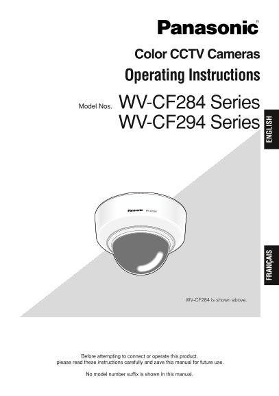
Color CCTV Cameras Operating Instructions Model Nos. WV-CF284 Series WV-CF294 Series WV-CF284 FR AN ÇA IS EN GL IS WV-CF284 is shown above. Before attempting to connect or operate this product, please...
Page 2
ENGLISH VERSION For Canada This Class A digital apparatus complies with CAUTION Canadian ICES-003. RISK OF ELECTRIC SHOCK DO NOT OPEN For U.S.A NOTE: This equipment has been tested and found to comply...
Page 3
Important Safety Instructions 1) Read these instructions. 2) Keep these instructions. 3) Heed all warnings. 4) Follow all instructions. 5) Do not use this apparatus near water. 6) Clean only with dry ...
Page 4
Limitation of Liability THIS PUBLICATION IS PROVIDED "AS IS" THIS PUBLICATION COULD INCLUDE WITHOUT WARRANTY OF ANY KIND, TECHNICAL INACCURACIES OR TYPO- EITHER EXPRESS OR IMPLIED, INCLUDING...
Page 5
Preface The WV-CF284/WV-CF294 series are surveillance color CCTV cameras equipped with a 1/4- inch CCD solid-state image sensor with 768 of horizontal pixels. These cameras can be mounted on a ceiling...
Page 6
CONTENTS Important Safety Instructions ..................................................................................................... Limitation of Liability ......................................
Page 7
Precautions This apparatus has no power switch. Cleaning the camera body Power is supplied from an external 12 V Turn the power off when cleaning of the cam- DC/24 V AC power-supply device. Refer to e...
Page 8
Use this product for indoor use only. Be sure to remove this apparatus if it is Do not expose this product to direct sunlight not in use. for hours and do not install the product near a heater or an a...
Page 9
Major Operating Controls and Their Functions B. S. BL B. S. BL D/ AL D/ AL FFO EL FFO EL LOCK LOCK B. S. BL B. S. BL D/ AL D/ AL WV-CF284 AF FFO EL WV-CF294 AF FFO EL LOCK LOCK WV-CF294TWV-CF284T Vide...
Page 10
Dip switch Light control mode selector [ALC/ELC] Selects ON/OFF of light control mode, ALC: Adjusts the lens iris automatically. backlight compensation, Adaptive Black ELC: This mode is used for manua...
Page 11
Installations and Connections Caution: ONLY CONNECT THIS TO 24 V AC OR 12 V DC CLASS 2 POWER SUPPLY. The following installation should be made by qualified service personnel or system installers. Prep...
Page 12
Disassembling the Camera mark four screw positions with a pen. 3. Mount the camera on the wall/ceiling 1. Remove the top cover. with 4 screws (procured locally). Adjust the marker of this unit to &quo...
Page 13
holes and connect them to the twisted Models Cable type Extensible length pair wire terminals (+) and (–). Approx. 250 m RG-59/U (3C-2V) {825 ft} Approx. 500 m RG-6/U (5C-2V) WV-CF284/ {1 650 ft} CF29...
Page 14
Power connection Resistance of copper wire [at 20 °C {68 °F}] Connect the three-conductor cable of the Copper wire #24 #22 #20 #18 size (AWG) (0.22 mm2) (0.33 mm2) (0.52 mm2) (0.83 mm2) camera to the ...
Page 15
Panning table Azimuth adjuster Indication <WV-CF284> .S LC Indication /N LOCK FF LC Panning table lock screw Rotating Rotating angle: angle: –100° +100° <WV-CF284> Indication i : CCD up-si...
Page 16
<Adjustment for WV-CF294/CF294T> Subjects with laterally parallel lines Loosen the zoom lock lever and move (e.g. shutters) the lever between TELE and WIDE to Foggy or dirty dome cover obtain th...
Page 17
Assembling the Camera Rotate the top cover clockwise to adjust the marker to "LOCK". 1. Mount the top cover. Adjust the marker of this unit to "INSERT" of the "DOME COVER"...
Page 18
Specifications Power source and power consumption: 24 V AC 60 Hz, 2.7 W 12 V DC, 220 m A Image sensor: 1/4 inch interline transfer CCD Effective pixels: 768 (H) x 494 (V) Scanning area: 3.6 (H) x 2.7 ...
Page 19
Standard Accessories Operating Instructions (this book).................. 1 pc. Warranty card ................................................ 1 pc. The following is for installation. Top cover fixing...
Page 20
VERSION FRANÇAISE (FRENCH VERSION) CAUTION ATTENTION RISK OF ELECTRIC SHOCK DO NOT OPEN RISQUE DE CHOCS ELECTRIQUES NE PAS OUVRIR ATTENTION: AFIN DE PRÉVENIR LE RISQUE DE CHOCS ÉLECTRIQUES, NE PAS RET...
Page 21
Instructions de sécurité importantes 1) Veiller à lire ces instructions. 2) Conserver ces instructions. 3) Tenir compte de tous les avertissements. 4) Se conformer à toutes les instructions. 5) Ne pas...
Page 22
Limitation de responsabilité CETTE PUBLICATION EST FOURNIE CETTE PUBLICATION A PU INCLURE DES "COMME TEL" SANS GARANTIE DE TOUTE INEXACTITUDES TECHNIQUES OU DES SORTE, EXPRÈS OU IMPLICITE, É...
Page 23
Préface Les modèles des séries WV-CF284/WV-CF294 sont des caméras vidéo couleur de surveillance CCTV équipées d’un capteur d’image à dispositif à couplage de charges à l'état solide CCD de 1/4 de pouc...
Page 24
TABLE DES MATIÈRES Instructions de sécurité importantes .......................................................................................... Limitation de responsabilité ...........................
Page 25
Mesures de précaution Cet appareil ne possède aucun Manipuler la caméra vidéo délicatement. interrupteur d'alimentation. Ne jamais manipuler brutalement cette L‘alimentation est fournie par un disposi...
Page 26
Traînage Sujet lumineux Emplacement d’installation Pour toute assistance, prendre contact avec votre distributeur en cas d'incertitude de l’emplacement approprié dans votre environnement spécifique. S...
Page 27
Principaux organes de commande et fonctions B. S. BL B. S. BL D/ AL D/ AL FFO EL FFO EL LOCK LOCK B. S. BL B. S. BL D/ AL D/ AL WV-CF284 AF FFO EL WV-CF294 AF FFO EL LOCK LOCK WV-CF294TWV-CF284T Conne...
Page 28
Commutateur à positions multiples Sélecteur de mode de contrôle de Sélectionne ON/OFF du mode de lumière [ALC/ELC] commande d’éclairage, de la ALC: Ajuste automatiquement l’ouverture compensation d’éc...
Page 29
Installations et connexions Précaution: RACCORDER UNIQUEMENT CET APPAREIL À UNE SOURCE D’ALIMENTATION DE 24 V C.A. OU DE 12 V C.C. DE CLASSE 2. L’installation suivante doit être faite par un technicie...
Page 30
Démontage de la caméra ments de vis de fixation avec un crayon. 3. Installer la caméra vidéo sur un mur ou vidéo au plafond à l'aide des quatre vis de 1. Retirer le couvercle supérieur. fixation (que ...
Page 31
Connecteur de sortie vidéo Cordon d’alimentation Approx. 200 mm {7-7/8"} Approx. 8 mm {5/16"} .S LC FF LC LOCK Afin d’éviter toute erreur de court-circuit, les extrémités des fils non utilis...
Page 32
Connexion d’alimentation Résistance des fils de cuivre [à 20 °C {68 °F}] Raccorder le câble à trois conducteurs Calibre de fil de cuivre #24 #22 #20 #18 provenant de la caméra vidéo à (AWG) (0,22mm2) ...
Page 33
Table de balayage panoramique Dispositif de réglage d’azimut Indication <WV-CF284> .S LC Indication /N FF LC Vis de blocage de table de balayage panoramique Angle de Angle de rotation: rotation:...
Page 34
Remarque: Pour pouvoir changer Sujets extrêmement lumineux ou d’angle de vue en actionnant le lumière réfléchie levier de blocage du zoom, déplacer Sujets placés derrière une fenêtre également le levi...
Page 35
Assemblage de la caméra Faire pivoter le couvercle supérieur dans le sens des aiguilles d'une montre pour vidéo régler le marqueur sur la position 1. Installer le couvercle supérieur. "LOCK"...
Page 36
Caractéristiques techniques Source d’alimentation et puissance consommée: 24 V de courant alternatif, 60 Hz, 2,7 W 12 V de courant continu, 220 m A Capteur d'image: Dispositif à transfert de charges i...
Page 37
Accessoires standard Manuel d'utilisation (la présente brochure) 1 él. Carte de garantie ........................................................... 1 él. Les éléments suivants sont destinés à l'insta...
Page 40
Panasonic System Solutions Company, Unit Company of Panasonic Corporation of North America Security Systems www.panasonic.com/security For customer support, call 1.877.733.3689 Executive Office: Three...