Motorola MCCF33095 MC33095 User Manual
Summary
An advanced regulator control integrated circuit designed specifically for robust 12V alternator charging systems used in demanding automotive environments. It precisely manages field current while featuring comprehensive internal protections, including shorted field detection and temperature compensation. Manual coverage includes detailed electrical specifications, operational parameters, and comparative data for both highly durable Flip-Chip and Surface Mount packages, accommodating extreme temperatures up to 170°C. This IC is crucial for automotive electronics engineers developing reliable and efficient vehicle charging solutions.
Page 1 Text Content
查询MC33096供应商
Order this document by MCCF33095/D
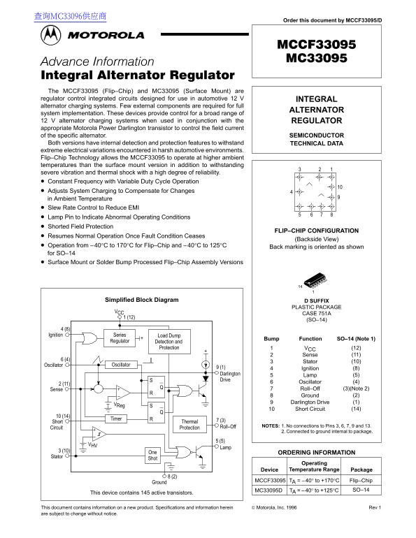
The MCCF33095 (Flip–Chip) and MC33095 (Surface Mount) are regulator control integrated circuits designed for use in automotive 12 V INTEGRAL alternator charging systems. Few external components are required for full
ALTERNATOR
system implementation. These devices provide control for a broad range of 12 V alternator charging systems when used in conjunction with the REGULATOR appropriate Motorola Power Darlington transistor to control the field current of the specific alternator. SEMICONDUCTOR Both versions have internal detection and protection features to withstand TECHNICAL DATA extreme electrical variations encountered in harsh automotive environments. Flip–Chip Technology allows the MCCF33095 to operate at higher ambient temperatures than the surface mount version in addition to withstanding severe vibration and thermal shock with a high degree of reliability. Constant Frequency with Variable Duty Cycle Operation Adjusts System Charging to Compensate for Changes in Ambient Temperature Slew Rate Control to Reduce EMI Lamp Pin to Indicate Abnormal Operating Conditions Shorted Field Protection
FLIP–CHIP CONFIGURATION
Resumes Normal Operation Once Fault Condition Ceases
(Backside View)
Operation from –40°C to 170°C for Flip–Chip and –40°C to 125°C Back marking is oriented as shown for SO–14 Surface Mount or Solder Bump Processed Flip–Chip Assembly Versions
Simplified Block Diagram D SUFFIX
PLASTIC PACKAGE
CASE 751A
(SO–14)
4 (8) Ignition Series Load Dump
Bump Function SO–14 (Note 1)
Regulator Detection and
Protection VCC (12)
Sense (11)
Stator (10)
Oscillator Oscillator
9 (1) Ignition (8) Darlington (5)
Drive
Oscillator (4)
Sense Roll–Off (3)(Note 2) Ground (2) Darlington Drive (1)
Short Circuit (14)
Timer
Short Thermal 7 (3)
Roll–Off NOTES: 1. No connections to Pins 3, 6, 7, 9 and 13.
Circuit Protection
2. Connected to ground internal to package.
One ORDERING INFORMATION
Stator
Operating Device Temperature Range Package
MCCF33095 TA = –40° to +170°C Flip–Chip
Ground
MC33095D TA = –40° to +125°C SO–14
This device contains 145 active transistors.
This document contains information on a new product. Specifications and information herein Motorola, Inc. 1996 Rev 1
are subject to change without notice. 1MOTOROLA ANALOG IC DEVICE DATA
Page Summary Contents For Motorola MCCF33095 MC33095 User Manual
Manual Details
| Brand | Motorola |
|---|---|
| Pages | 12 |
| File Size | 169.16 KB |
| Published | June 05, 2026 |
Enter the captcha to get the download link:

Frequently Asked Questions
What is the key difference in reliability between the Flip-Chip and Surface Mount versions?
The Flip–Chip technology allows the MCCF33095 to operate at higher ambient temperatures and withstand severe vibration and thermal shock with high reliability.
What is the maximum operating temperature range for these components?
The Flip–Chip version operates from –40°C to +170°C, while the Surface Mount (SO–14) operates from –40°C to +125°C.
What purpose does the device serve in an alternator charging system?
It is a regulator control integrated circuit used for controlling the field current of specific automotive 12 V INTEGRAL alternator charging systems.
Are external components required for full ALTERNATOR system implementation?
No, the text states that few external components are required for full ALTERNATOR system implementation when using this device.