Motorola MCCF33094 User Guide
Summary
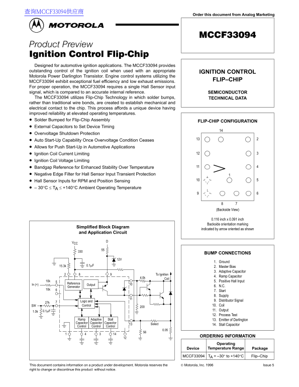
This advanced Darlington Transistor is engineered for reliable automotive ignition control, supporting engine systems that require exceptional fuel efficiency and low emissions. Utilizing Flip-Chip Technology, it provides enhanced reliability at high operating temperatures while offering vital features like overvoltage shutdown protection and auto start-up capability. This technical manual details the device's operational parameters (-30°C to +140°C), technical data, block diagrams, and integration into professional engine control systems for automotive developers.
Page 1 Text Content
查询MCCF33094供应商
Order this document from Analog Marketing
Designed for automotive ignition applications. The MCCF33094 provides outstanding control of the ignition coil when used with an appropriate
IGNITION CONTROL
Motorola Power Darlington Transistor. Engine control systems utilizing the
FLIP–CHIP
MCCF33094 exhibit exceptional fuel efficiency and low exhaust emissions. For proper operation, the MCCF33094 requires a single Hall Sensor input signal, which is compared to an accurate internal reference. SEMICONDUCTOR The MCCF33094 utilizes Flip-Chip Technology in which solder bumps, TECHNICAL DATA rather than traditional wire bonds, are created to establish mechanical and electrical contact to the chip. This process affords a unique device having improved reliability at elevated operating temperatures. Solder Bumped for Flip-Chip Assembly
FLIP-CHIP CONFIGURATION
External Capacitors to Set Device Timing Overvoltage Shutdown Protection Auto Start-Up Capability Once Overvoltage Condition Ceases Allows for Push Start-Up in Automotive Applications Ignition Coil Current Limiting Ignition Coil Voltage Limiting Bandgap Reference for Enhanced Stability Over Temperature Negative Edge Filter for Hall Sensor Input Transient Protection Hall Sensor Inputs for RPM and Position Sensing 30°C ≤ TA ≤ +140°C Ambient Operating Temperature
(Backside View)
0.116 inch x 0.091 inch Backside orientation marking
Simplified Block Diagram
indicated by arrow oriented as shown
and Application Circuit
BUMP CONNECTIONS
1. Ground
2. Master Bias 3. Adaptive Capacitor
To Ignition
4. Ramp Capacitor
4.0k Coil
10k 5. Positive Hall Input
Reference
In (+) Output
Generator 6. N.C.
7. Start 8. Supply Logic and 9. Distributor Signal
SW Control 10. Coil 0.1µF 11. Output
12. Process Test
Ramp Adaptive Stall 13. Emitter of Darlington Capacitor Capacitor Capacitor
Select 14. Stall Capacitor
Control Control Control
ORDERING INFORMATION Operating Device Temperature Range Package
MCCF33094 TA = –30° to +140°C Flip–Chip
This document contains information on a product under development. Motorola reserves the Motorola, Inc. 1996 Issue 5
right to change or discontinue this product without notice. 1MOTOROLA ANALOG IC DEVICE DATA
Page Summary Contents For Motorola MCCF33094 User Guide
Manual Details
| Brand | Motorola |
|---|---|
| Pages | 2 |
| File Size | 50.48 KB |
| Published | May 31, 2026 |
Enter the captcha to get the download link:

Frequently Asked Questions
What is the operational temperature range for this device?
The ambient operating temperature range supports models from -30°C to +140°C.
What type of input signal does the MCCF33094 require?
It requires a single Hall Sensor input signal, which is compared against an accurate internal reference.
How does the device achieve improved reliability?
It utilizes Flip-Chip Technology, forming solder bumps for electrical contact, affording reliable operation at elevated temperatures.
What safety features are integrated into this unit?
The MCCF33094 includes Overvoltage Shutdown Protection and a Negative Edge Filter for Hall Sensor Input transient protection.