# A B C D E F G H I J K L M N O P Q R S T U V W X Y Z

Motorola MC33030 User Guide

Summary

The MC33033 is a high-performance monolithic brushless DC motor controller designed for efficient open loop and three/four phase semiconductor motor control applications. This manual provides comprehensive technical specifications, electrical characteristics, and operational guides necessary for system integration. It is essential reading for professional engineers and developers working on complex electro-mechanical systems who require reliable power MOSFET driving and built-in safety features like undervoltage lockout and current limiting.
📄 Preview PAGE OF 24

Page 1 Text Content

查询MC33033供应商

Order this document by MC33033/D

BRUSHLESS DC

The MC33033 is a high performance second generation, limited feature,

monolithic brushless dc motor controller which has evolved from Motorola′s MOTOR CONTROLLER

full featured MC33034 and MC33035 controllers. It contains all of the active functions required for the implementation of open loop, three or four phase

SEMICONDUCTOR

motor control. The device consists of a rotor position decoder for proper

TECHNICAL DATA

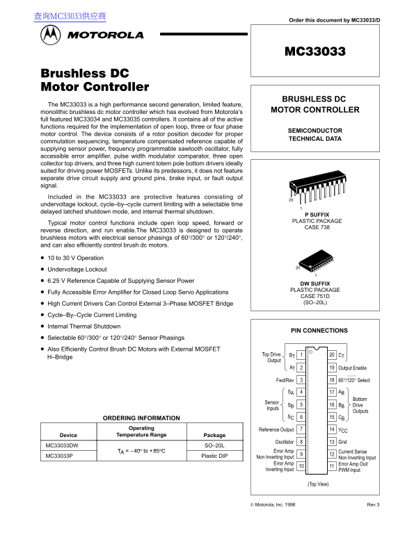
commutation sequencing, temperature compensated reference capable of supplying sensor power, frequency programmable sawtooth oscillator, fully accessible error amplifier, pulse width modulator comparator, three open collector top drivers, and three high current totem pole bottom drivers ideally suited for driving power MOSFETs. Unlike its predessors, it does not feature separate drive circuit supply and ground pins, brake input, or fault output signal. Included in the MC33033 are protective features consisting of undervoltage lockout, cycle–by–cycle current limiting with a selectable time delayed latched shutdown mode, and internal thermal shutdown.

P SUFFIX PLASTIC PACKAGE

Typical motor control functions include open loop speed, forward or

CASE 738

reverse direction, and run enable.The MC33033 is designed to operate brushless motors with electrical sensor phasings of 60°/300° or 120°/240°, and can also efficiently control brush dc motors.

10 to 30 V Operation Undervoltage Lockout 6.25 V Reference Capable of Supplying Sensor Power

DW SUFFIX PLASTIC PACKAGE

Fully Accessible Error Amplifier for Closed Loop Servo Applications

CASE 751D High Current Drivers Can Control External 3–Phase MOSFET Bridge (SO–20L)

Cycle–By–Cycle Current Limiting Internal Thermal Shutdown

PIN CONNECTIONS

Selectable 60°/300° or 120°/240° Sensor Phasings Also Efficiently Control Brush DC Motors with External MOSFET

BTTop Drive CT

H–Bridge

Output

AT Output Enable2

60°/120° Select Fwd/Rev

SA AB

SB 5Sensor BB Drive

Inputs

Outputs

SC CB

ORDERING INFORMATION

Operating

Reference Output VCC

Device Temperature Range Package

Oscillator Gnd

MC33033DW SO–20L

TA –40° to +85°C Error Amp Current Sense

MC33033P Plastic DIP Non Inverting Input

Non Inverting Input

Error Amp Error Amp Out/ Inverting Input PWM Input

(Top View)

Motorola, Inc. 1996 Rev 3

1MOTOROLA ANALOG IC DEVICE DATA

Page Summary Contents For Motorola MC33030 User Guide

Page 1 查询MC33033供应商 Order this document by MC33033/D BRUSHLESS DC The MC33033 is a high performance second generation, limited feature, monolithic brushless dc motor controller which has evolved from Motorol...
Page 2 MC33033 Representative Schematic Diagram Rotor Position Decoder FWR/REV Motor Enable Undervoltage VCC Output Lockout Buffers Reference Regulator Speed Set Error Amp Thermal Faster Shutdown Oscillator ...
Page 3 MC33033 MAXIMUM RATINGS Rating Symbol Value Unit Power Supply Voltage VCC Digital Inputs (Pins 3, 4, 5, 6, 18, 19) Vref Oscillator Input Current (Source or Sink) IOSC m A Error Amp Input Voltage Range...
Page 4 MC33033 ELECTRICAL CHARACTERISTICS (continued) (VCC = 20 V, RT = 4.7 k, CT = 10 n F, TA = 25°C, unless otherwise noted.) Characteristic Symbol Min Typ Max Unit OSCILLATOR SECTION Oscillator Frequency ...
Page 5 MC33033 Figure 1. Oscillator Frequency versus Figure 2. Oscillator Frequency Change , O TP VO LT AG (V L, PE –L VO LT AG AI (d B) f O SC IL LA TO EQ EN (k z) Timing Resistor versus Temperature VCC = 2...
Page 6 MC33033 Figure 7. Reference Output Voltage Change Figure 8. Reference Output Voltage versus TT IV ES PO SE IM (n s) ∆V AL IZ ED EF ER EN VO LT AG AN (m V) ef ,R EF ER EN TP VO LT AG AN (m V) versus Ou...
Page 7 MC33033 Figure 13. Top Drive Output Waveform Figure 14. Bottom Drive Output Waveform TP VO LT AG TP VO LT AG VCC = 20 V CL = 1.0 n F TA = 25°C VCC = 20 V RL = 1.0 k CL = 15 p F TA = 25°C , P ER PP LY ...
Page 8 MC33033 PIN FUNCTION DESCRIPTION Pin Symbol Description 1, 2, 20 BT, AT, CT These three open collector Top Drive Outputs are designed to drive the external upper power switch transistors. Fwd//Rev The...
Page 9 MC33033 INTRODUCTION effect the commutation sequence is reversed and the motor changes directional rotation. The MC33033 is one of a series of high performance Motor on/off control is accomplished by ...
Page 10 MC33033 Figure 18. Representative Block Diagram SBSensor Inputs Rotor Position BT Drive Decoder 40 k Outputs Foward/Reverse 60°/120° Select Output Enable Undervoltage Lockout Reference Regulator 8.9 V...
Page 11 MC33033 Figure 19. Three Phase, Six Step Commutation Truth Table (Note 1) Inputs (Note 2) Outputs (Note 3) Sensor Electrical Phasing (Note 4) Top Drives Bottom Drives 60° 120° Current SA SB SC SA SB S...
Page 12 MC33033 Figure 20. PWM Timing Diagram Figure 21. Reference Output Buffers Capacitor CT Error Amp Out/ MPS PWM Input U01A Current Sense Control Sensor Input Circuitry Power Latch “Set” Inputs UVLO1436 ...
Page 13 MC33033 Figure 24. Current Waveform Spike Suppression Figure 25. MOSFET Drive Precautions Vo lta ge (V oo st Series gate resistor Rg will damp any high frequency oscillations caused The addition of th...
Page 14 MC33033 Figure 30. Controlled Acceleration/Deceleration Figure 31. Digital Speed Controller REF VCC REF Enable 108 k R1 BCD 77.6 k EA Inputs P1 Q4 Increase 63.6 k P0 Q3 PWM Speed Gnd Q0 Resistor R1 wi...
Page 15 MC33033 Figure 34. Three Phase, Six Step, Full Wave Motor Controller Rotor Position Decoder FWR/REV Enable Undervoltage VM Motor Lockout Reference Regulator Speed Set Error Amp Thermal Q5 Faster Shutd...
Page 16 MC33033 Figure 35. Three Phase, Six Step, Full Wave Commutation Waveforms Rotor Electrical Position (Degrees) Sensor Inputs 60°/120° Select Pin Open SC Sensor Inputs SB 60°/120° Select Pin Grounded To...
Page 17 MC33033 Figure 36 shows a three phase, three step, half wave motor winding. Current flow is unidirectional or half wave because controller. This configuration is ideally suited for automobile only one...
Page 18 MC33033 Three Phase Closed Loop Controller The MC33033, by itself, is capable of open loop motor train of pulses present at Pin 5 of the MC33039 are speed control. For closed loop speed control, the M...
Page 19 MC33033 Sensor Phasing Comparison There are four conventions used to establish the relative In this data sheet, the rotor position has always been given en so le ct ri ca l P as in phasing of the sens...
Page 20 MC33033 ig re 1. as e, te , F ll av tr lle ot or Po si tio ec od er FW /R EV En ab le nd er vo lta ge Lo ck ou ef er en ce eg ul at or Er ro r A Th er al Sh ut do sc illa to Li it MOTOROLA ANALOG IC D...
Page 21 MC33033 Figure 42. Four Phase, Four Step, Full Wave Commutation Waveforms Rotor Electrical Position (Degrees) Sensor Inputs 60°/120° Select Pin Open Top Drive Outputs Bottom Drive Outputs Conducting P...
Page 22 MC33033 ig re 3. as e, te , H al av to tr lle ot or Po si tio ec od er FW /R EV En ab le nd er vo lta ge Lo ck ou ef er en ce eg ul at or Er ro r A Th er al Sh ut do sc illa to Li it MOTOROLA ANALOG I...
Page 23 MC33033 Brush Motor Control Though the MC33033 was designed to control brushless fly, using the normal Forward/Reverse switch, and not have to dc motors, it may also be used to control dc brush–type c...
Page 24 MC33033 OUTLINE DIMENSIONS P SUFFIX PLASTIC PACKAGE CASE 738–03 ISSUE E NOTES: 1. DIMENSIONING AND TOLERANCING PER ANSI Y14.5M, 1982. 2. CONTROLLING DIMENSION: INCH. 3. DIMENSION L TO CENTER OF LEAD W...

Manual Details

Brand Motorola
Pages 24
File Size 536.05 KB
Published May 27, 2026
94 views

Enter the captcha to get the download link:

captcha

Frequently Asked Questions

What motor types can the MC33033 control?

It is designed for brushless motors with sensor phasings of 60°/300° or 120°/240°, and it can also efficiently control brush DC motors.

What protective features does the MC33033 include?

The device includes undervoltage lockout, cycle–by–cycle current limiting (with delayed shutdown), and internal thermal shutdown.

What is the recommended operating voltage range?

The MC33033 is designed to operate between 10 V and 30 V.

How can I configure the sensor phasings?

You must select between 60°/300° or 120°/240° sensor phasings, which are selectable on the device.