Motorola MC10EL32 MC100EL32 User Guide (1)
Summary
This advanced integrated circuit is a high-speed dual divider (Q/2), engineered for critical system clocking applications. The corresponding manual provides comprehensive technical data, detailing DC and AC electrical characteristics, precise timing diagrams, and pin assignments. It supports various interfacing modes, including differential, single-ended, or AC coupled inputs. Ideal for hardware engineers and electronics designers requiring reliable, high-bandwidth logic transitions in demanding digital systems.
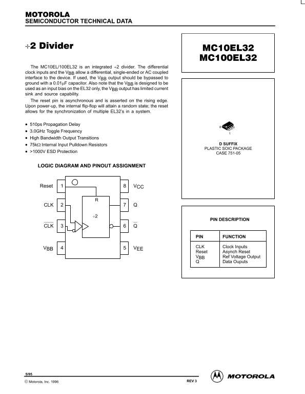
Page 1 Text Content
SEMICONDUCTOR TECHNICAL DATA
The MC10EL/100EL32 is an integrated ÷2 divider. The differential clock inputs and the VBB allow a differential, single-ended or AC coupled interface to the device. If used, the VBB output should be bypassed to ground with a 0.01µF capacitor. Also note that the VBB is designed to be used as an input bias on the EL32 only, the VBB output has limited current sink and source capability. The reset pin is asynchronous and is asserted on the rising edge. Upon power-up, the internal flip-flop will attain a random state; the reset allows for the synchronization of multiple EL32’s in a system.
510ps Propagation Delay 3.0GHz Toggle Frequency High Bandwidth Output Transitions
75kΩ Internal Input Pulldown Resistors D SUFFIX PLASTIC SOIC PACKAGE
>1000V ESD Protection
CASE 751-05
LOGIC DIAGRAM AND PINOUT ASSIGNMENT
Reset VCC
PIN DESCRIPTION
PIN FUNCTION
CLK Clock Inputs
VBB VEE
Reset Asynch Reset VBB Ref Voltage Output
Data Ouputs
3–1 REV 3 Motorola, Inc. 1996
Page Summary Contents For Motorola MC10EL32 MC100EL32 User Guide (1)
Manual Details
| Brand | Motorola |
|---|---|
| Pages | 4 |
| File Size | 53.25 KB |
| Published | May 29, 2026 |
Enter the captcha to get the download link:

Frequently Asked Questions
What is the purpose of the reset pin?
The reset pin is asynchronous and allows for the synchronization of multiple EL32 chips in a system, although the internal flip-flop will attain a random state upon power-up.
How should the V output be handled if used?
If used, the V output should be bypassed to BB ground with a 0.01μF capacitor, and remember it is limited for current sink/source capability.
What are the minimum operating voltage ranges for the supply?
The power supply (VCC) must operate between 25 mA and 30 mA in typical conditions, while the voltage range is provided across various temperatures, e.g., -5.2 V to -4.75 V.
What are the guaranteed minimum input swing parameters?
The AC parameters are guaranteed for a minimum input swing of 150 mV PP.