Motorola MC100LVEL30 MC100EL30 User Guide (1)
Summary
This comprehensive datasheet details the MC100LVEL30/MC100EL30, a high-speed triple master–slave D flip flop featuring differential outputs. Ideal for advanced digital system design, this component provides precise data latching and asynchronous Set/Reset control. The manual covers critical technical specifications, including electrical characteristics (DC/AC), propagation delays, timing diagrams, and package dimensions. It is essential reading for electronic engineers and circuit designers integrating performance-critical logic into demanding high-speed circuits operating at various voltage levels.
Page 1 Text Content
SEMICONDUCTOR TECHNICAL DATA
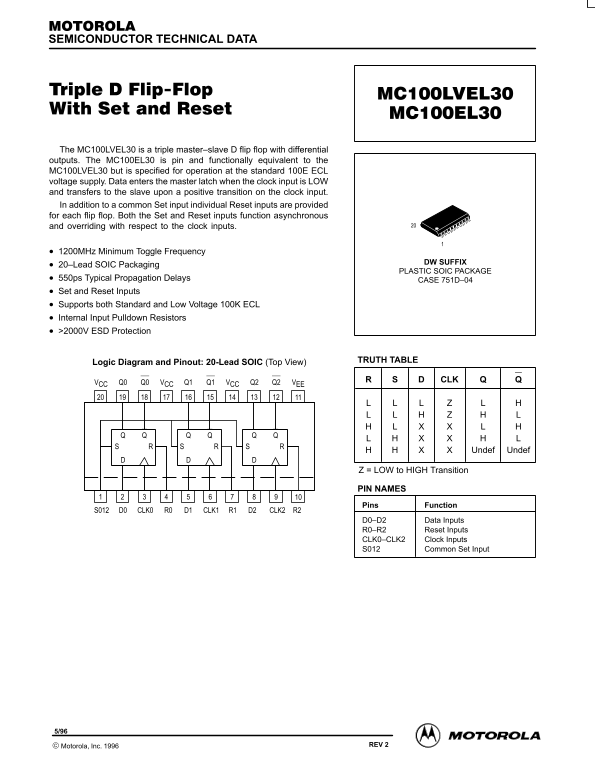
The MC100LVEL30 is a triple master–slave D flip flop with differential outputs. The MC100EL30 is pin and functionally equivalent to the MC100LVEL30 but is specified for operation at the standard 100E ECL voltage supply. Data enters the master latch when the clock input is LOW and transfers to the slave upon a positive transition on the clock input. In addition to a common Set input individual Reset inputs are provided for each flip flop. Both the Set and Reset inputs function asynchronous and overriding with respect to the clock inputs.
1200MHz Minimum Toggle Frequency
DW SUFFIX
20–Lead SOIC Packaging
PLASTIC SOIC PACKAGE
550ps Typical Propagation Delays CASE 751D–04 Set and Reset Inputs Supports both Standard and Low Voltage 100K ECL Internal Input Pulldown Resistors >2000V ESD Protection
TRUTH TABLE
Logic Diagram and Pinout: 20-Lead SOIC (Top View)
VCC Q0 Q0 VCC Q1 Q1 VCC Q2 Q2 VEE
QQ QQ QQ RS RS RS
Undef Undef
Z = LOW to HIGH Transition
PIN NAMES
Pins Function
D0 CLK0 R0 D1 CLK1S012 R1 D2 CLK2 R2
D0–D2 Data Inputs R0–R2 Reset Inputs CLK0–CLK2 Clock Inputs S012 Common Set Input
4–1 REV 2 Motorola, Inc. 1996
Page Summary Contents For Motorola MC100LVEL30 MC100EL30 User Guide (1)
Manual Details
| Brand | Motorola |
|---|---|
| Pages | 4 |
| File Size | 63.88 KB |
| Published | June 06, 2026 |
Enter the captcha to get the download link:

Frequently Asked Questions
How does data transfer through this flip flop?
Data enters the master latch when the clock input is LOW and transfers to the slave upon a positive transition on the clock input.
Do the Set or Reset inputs require the clock signal?
No, both Set and Reset function asynchronously and override with respect to the clock inputs.
What is the maximum operating frequency?
The device supports a maximum toggle frequency of 1.2 GHz (typical value at 25°C).