# A B C D E F G H I J K L M N O P Q R S T U V W X Y Z

LINEAR TECHNOLOGY LTC4267 User's Guide

Summary

This detailed manual describes the LTC4267, a highly integrated IC designed for complete power management solutions in IEEE 802.3af Power over Ethernet (PoE) applications. It combines an advanced PD interface with an onboard switching regulator, offering crucial features like programmable classification current, dual-level inrush current limiting, and thermal protection. Ideal for engineers developing low-power networking equipment—such as IP phones, Wi-Fi access points, and security cameras—this component ensures reliable and efficient power delivery to various powered devices.
📄 Preview PAGE OF 32

Page 1 Text Content

LTC4267

Power over Ethernet

IEEE 802.3af PD Interface with Integrated Switching Regulator

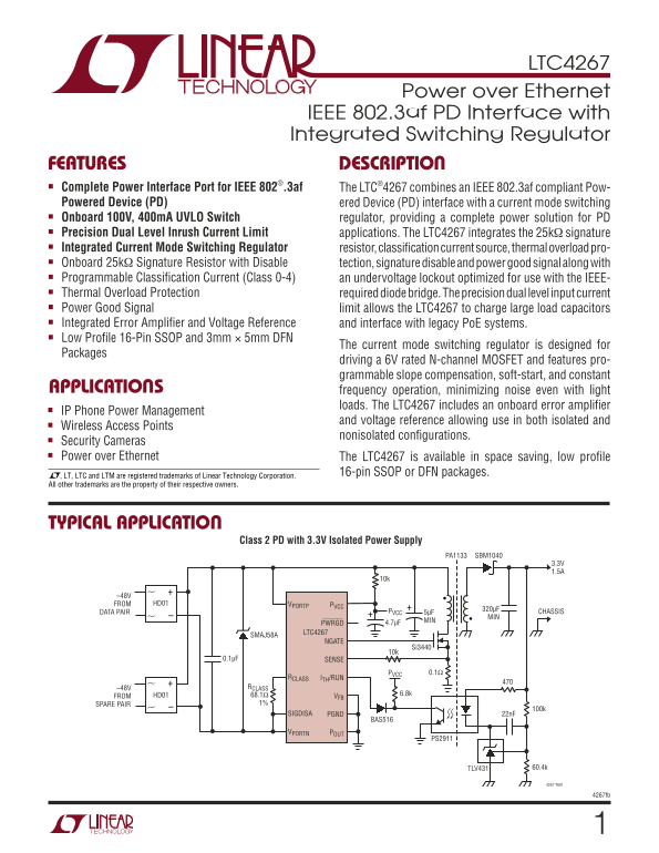
FEATURES DESCRIPTIO ■ Complete Power Interface Port for IEEE 802®.3af

The LTC®4267 combines an IEEE 802.3af compliant Pow-

Powered Device (PD) ered Device (PD) interface with a current mode switching ■ Onboard 100V, 400m A UVLO Switch

regulator, providing a complete power solution for PD

■ Precision Dual Level Inrush Current Limit

applications. The LTC4267 integrates the 25kΩ signature

■ Integrated Current Mode Switching Regulator

resistor, classifi cation current source, thermal overload pro-

■ Onboard 25kΩ Signature Resistor with Disable

tection, signature disable and power good signal along with

■ Programmable Classifi cation Current (Class 0-4)

an undervoltage lockout optimized for use with the IEEE-

■ Thermal Overload Protection

required diode bridge. The precision dual level input current

■ Power Good Signal

limit allows the LTC4267 to charge large load capacitors

■ Integrated Error Amplifi er and Voltage Reference

and interface with legacy Po E systems.

■ Low Profi le 16-Pin SSOP and 3mm × 5mm DFN

The current mode switching regulator is designed for

Packages

driving a 6V rated N-channel MOSFET and features pro- grammable slope compensation, soft-start, and constant

APPLICATIO frequency operation, minimizing noise even with light

loads. The LTC4267 includes an onboard error amplifi er

■ IP Phone Power Management

and voltage reference allowing use in both isolated and

■ Wireless Access Points

nonisolated confi gurations.

■ Security Cameras

■ Power over Ethernet

The LTC4267 is available in space saving, low profi le 16-pin SSOP or DFN packages.

, LT, LTC and LTM are registered trademarks of Linear Technology Corporation. All other trademarks are the property of their respective owners.

TYPICAL APPLICATIO

Class 2 PD with 3.3V Isolated Power Supply

PA1133 SBM1040

FROM HD01 VPORTP PVCC

PVCC 320µF

DATA PAIR 5µF CHASSIS

PWRGD 4.7µF

LTC4267

SMAJ58A

NGATE

Si3440 10k

0.1µF SENSE

PVCC 0.1Ω

RCLASS ITH/RUN

–48V RCLASS

HD01 68.1Ω 6.8k

FROM VFB

SPARE PAIR 1%

SIGDISA PGND 22n F

BAS516

VPORTN POUT

PS2911

TLV431 60.4k

4267 TA01

4267fb

Page Summary Contents For LINEAR TECHNOLOGY LTC4267 User's Guide

Page 1 LTC4267 Power over Ethernet IEEE 802.3af PD Interface with Integrated Switching Regulator FEATURES DESCRIPTIO ■ Complete Power Interface Port for IEEE 802®.3af The LTC®4267 combines an IEEE 802.3af co...
Page 2 LTC4267 ABSOLUTE AXI RATI GS (Note 1) VPORTN with Respect to VPORTP Voltage ... 0.3V to –100V SENSE to PGND Voltage .............................. –0.3V to 1V POUT, SIGDISA, ⎯P⎯W⎯R ⎯G⎯D NGATE Peak Out...
Page 3 LTC4267 The ● denotes the specifi cations which apply over the full operating ELECTRICAL CHARACTERISTICS temperature range, otherwise specifi cations are at TA = 25°C. (Note 3) SYMBOL PARAMETER CONDIT...
Page 4 LTC4267 ELECTRICAL CHARACTERISTICS The ● denotes the specifi cations which apply over the full operating temperature range, otherwise specifi cations are at TA = 25°C. (Note 3) SYMBOL PARAMETER CONDIT...
Page 5 G_ OU (V IN PU CU RR EN (m A) IN PU CU RR EN (m A) LTC4267 TYPICAL PERFOR CE CHARACTERISTICSA Input Current vs Input Voltage 25k Detection Range Input Current vs Input Voltage Input Current vs Input V...
Page 6 VO LT AG (m V) OS CI LL AT OR RE QU EN CY (k Hz LTC4267 TYPICAL PERFOR A CE CHARACTERISTICS Reference Voltage vs Reference Voltage vs Oscillator Frequency vs Temperature Supply Voltage Temperature PVC...
Page 7 ST AR T- UP UP PL CU RR EN (µ A) LTC4267 TYPICAL PERFOR A CE CHARACTERISTICS SE NS PI VO LT AG (m V) Start-Up IPVCC Supply Current vs ITH/RUN Shutdown Threshold vs ITH/RUN Start-Up Current Source Temp...
Page 8 LTC4267 PI FU CTIO S (GN/DHC) ITH/RUN (Pin 2/Pin 1): Current Threshold/Run Input. This ⎯P⎯W⎯R⎯G⎯D (Pin 11/Pin 11): Power Good Output, Open-Drain. pin performs two functions. It serves as the switching...
Page 9 LTC4267 BLOCK DIAGRAM VPORTP SIGDISA PVCC CLASSIFICATION CURRENT LOAD SHUTDOWN COMPARATOR 1.237V 0.3µA 0.28V PVCC < VTURNON UNDERVOLTAGE 9k SHUNT LOCKOUT EN REGULATOR RCLASS SIGNATURE REFERENCE RES...
Page 10 LTC4267 APPLICATIO S I FOR ATIO specifi ed to avoid corrupting the 25kΩ signature resistor DETECTION V1 TIME DETECTION V2 while also saving board space and cost. In addition, the in- –10 CLASSIFICATIO...
Page 11 LTC4267 APPLICATIO S I FOR ATIO Series Diodes The signature range extends below the IEEE range to ac- commodate the voltage drop of the two diodes. The IEEE The IEEE 802.3af-defi ned operating modes f...
Page 12 LTC4267 APPLICATIO S I FOR ATIO CURRENT PATH LTC4267 VPORTP LTC4267 SIGNATURE DISABLE PROBING TO VOLTAGE 25k SIGNATURE VPORTPRCLASS PSE SOURCE RESISTOR –15.5V TO –20.5V SIGDISA 16k CONSTANT RCLASS LOA...
Page 13 LTC4267 APPLICATIO S I FOR ATIO the classifi cation current is reenabled. C1 will discharge limit because the load capacitor is charged with a current through the PD circuitry and the POUT pin will go...
Page 14 LTC4267 APPLICATIO S I FOR ATIO R9 100k LTC4267 PWRGD R9 Q1 ITH/RUN THERMAL SHUTDOWN VPORTPITH/RUN 100k 2N7002 ITH/RUN LTC3803 UVLO PSE PWRGD C17 LTC4267 C1 R18 C15 TO C1 5µF 10k 0.047µF PSE 5µF 100V ...
Page 15 LTC4267 APPLICATIO S I FOR ATIO temperature exceeds the overtemperature trip point, the and an internal error amplifi er that can be enabled for this current is reduced to zero and very little power i...
Page 16 LTC4267 APPLICATIO S I FOR ATIO The undervoltage lockout mechanism on PVCC prevents Adjustable Slope Compensation the LTC4267 switching regulator from trying to drive the The LTC4267 switching regulat...
Page 17 LTC4267 APPLICATIO S I FOR ATIO Diode Bridge falls into and then select the appropriate value of RCLASS from Table 2. If a unique load current is required, the value IEEE 802.3af allows power wiring i...
Page 18 LTC4267 APPLICATIO S I FOR ATIO RJ45 TX+ T1 BR1 HD01 RX+ TO PHY PULSE H2019 VPORTP SPARE+ HD01 C14 LTC4267 0.1µF SMAJ58A 100V SPARE– TVS VPORTN Figure 9. PD Front End with Isolation Transformer, Diode...
Page 19 LTC4267 APPLICATIO S I FOR ATIO Signature Disable Interface output voltage reaches its fi nal value, the input current limit will be restored to its nominal value. To disable the 25kΩ signature resist...
Page 20 LTC4267 APPLICATIO S I FOR ATIO Choose resistance values for R1 and R2 to be as large as selecting the transformer turns ratio. The PD designer possible to minimize any effi ciency loss due to the sta...
Page 21 LTC4267 APPLICATIO S I FOR ATIO ISOLATED DESIGN EXAMPLE D1 VPORTP T1 RSTART LSECLPRI COUT DATA PAIR CPVCC VPORTP NGATE Q1 RCLASS RSL RLIM SENSE RCLASS LTC4267 –48V RSENSE SIGDISA SPARE PAIR PGND VPORT...
Page 22 LTC4267 APPLICATIO S I FOR ATIO Programmable Slope Compensation is providing virtually all the supply current required by the LTC4267 switching regulator. The LTC4267 switching regulator injects a ram...
Page 23 LTC4267 APPLICATIO S I FOR ATIO The shunt regulator can sink up to 5m A through the PVCC actual current needed to power the LTC4267 switching pin to PGND. The values of RSTART and CPVCC must be regula...
Page 24 LTC4267 APPLICATIO S I FOR ATIO of the LTC4267. In this case, it is necessary to ensure the LTC4267 user cannot access the terminals of the wall transformer jack on the PD since this would compromise ...
Page 25 LTC4267 APPLICATIO S I FOR ATIO OPTION 1: AUXILIARY POWER INSERTED BEFORE LTC4267 PD TX+ T1 D3 SMAJ58A TVS C14 RSTART BR1 0.1µF RX+ TO PHY HD01 100V RX– C1 VPORTP SPARE+ PVCC LTC4267 CPVCC HD01 PGND S...
Page 26 LTC4267 APPLICATIO S I FOR ATIO transformer voltage is higher than the PSE voltage, the to drive the ITH/RUN port below the shutdown threshold LTC4267 switching regulator will draw power from the (typ...
Page 27 LTC4267 APPLICATIO S I FOR ATIO with minimum trace lengths and minimum capacitance. or capacitive may inadvertently disable the signature In a nonisolated application, R1, and R2 should be placed resi...
Page 28 LTC4267 TYPICAL APPLICATIO S Class 3 PD with 5V Nonisolated Power Supply COILTRONICS CTX-02-15242 5V MIN 220k UPS840 MMBTA42 –48V BAS516 FROM HD01 VPORTP PVCC DATA PAIR LTC4267 SMAJ58A NGATE 150p F FD...
Page 29 LTC4267 TYPICAL APPLICATIO S Cl as PD ith rip le ut pu t I so la te Po er up pl T1T2 3. 3V AT .5 5µ F* Si IN 0k 2. 5V 0k BC X5 AT .5 PH PH BA S5 AT .5 CC PH TP CC C4 0. µF CH AS SI SM AJ BT BA T5 4S L...
Page 30 LTC4267 PACKAGE DESCRIPTIO DHC Package 16-Lead Plastic DFN (5mm × 3mm) (Reference LTC DWG # 05-08-1706) RECOMMENDED SOLDER PAD PITCH AND DIMENSIONS (DHC16) DFN 1103 NOTE: 1. DRAWING PROPOSED TO BE MAD...
Page 31 LTC4267 PACKAGE DESCRIPTIO GN Package 16-Lead Plastic SSOP (Narrow .150 Inch) (Reference LTC DWG # 05-08-1641) .009 (0.229) REF .254 MIN .150 – .165 .0015 .0250 BSC.0165 ± RECOMMENDED SOLDER PAD LAYOU...
Page 32 LTC4267 TYPICAL APPLICATION High-Effi ciency Class 3 PD with 3.3V Isolated Power Supply PULSE SBM1040 PA1136 3.3V 5µF* MIN CHASSIS MMTBA42 BAS516 MMSD4148 9.1V BAS516 –48V PVCC FROM VPORTP PVCC DATA P...

Manual Details

Brand Linear
Pages 32
File Size 2.00 MB
Published June 17, 2026
4 views

Enter the captcha to get the download link:

captcha

Frequently Asked Questions

What power standards does the LTC4267 comply with?

It is compliant with IEEE 802.3af for Power over Ethernet (PoE) and includes adjustable Class I/Run settings.

What protection features are integrated into the device?

The unit incorporates UVLO, programmable classification current limits, thermal overload protection, and a dual level input current limit.

Can this chip be used for various applications beyond typical PoE devices?

Yes, it is optimized for IP Phone Power Management, Wireless Access Points (WAPs), and Security Cameras in both isolated and non-isolated configurations.

What are the available operating temperature ranges for different packages?

The LTC4267C operates from 0°C to 70°C, while the outdoor version, LTC4267I, handles -40°C to 85°C.