LINEAR TECHNOLOGY LTC1840 Data Sheet
Summary
Technical documentation for Linear Technology LTC1840 dual fan controller featuring two 8-bit monotonic current output DACs, two programmable tachometer interfaces, and four general-purpose I/O pins configurable as digital inputs or open-drain pull-down outputs. Operating from 2.7V to 5.75V single supply, the device uses current DAC outputs to control external switching regulators for closed-loop fan speed control based on tachometer feedback. Includes 2-wire I²C and SMBus compatible serial inte
Page 1 Text Content
LTC1840
Dual Fan Controller with 2-Wire Interface
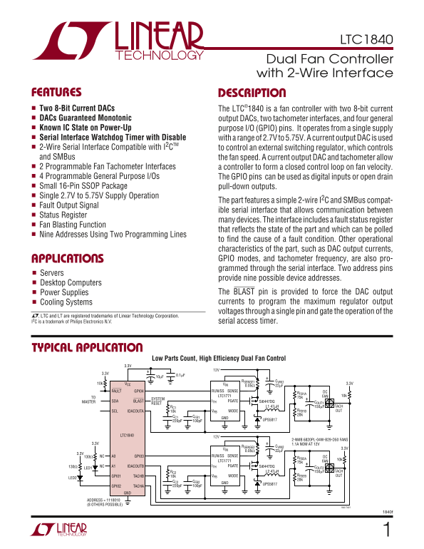
FEATURES DESCRIPTIO Two 8-Bit Current DACs The LTC®1840 is a fan controller with two 8-bit current DACs Guaranteed Monotonic output DACs, two tachometer interfaces, and four general Known IC State on Power-Up purpose I/O (GPIO) pins. It operates from a single supply Serial Interface Watchdog Timer with Disable with a range of 2.7V to 5.75V. A current output DAC is used 2-Wire Serial Interface Compatible with I2CTM to control an external switching regulator, which controls and SMBus the fan speed. A current output DAC and tachometer allow 2 Programmable Fan Tachometer Interfaces a controller to form a closed control loop on fan velocity. 4 Programmable General Purpose I/Os The GPIO pins can be used as digital inputs or open drain Small 16-Pin SSOP Package pull-down outputs. Single 2.7V to 5.75V Supply Operation
The part features a simple 2-wire I2C and SMBus compat-
Fault Output Signal
ible serial interface that allows communication between
Status Register
many devices. The interface includes a fault status register
Fan Blasting Function
that reflects the state of the part and which can be polled
Nine Addresses Using Two Programming Lines
to find the cause of a fault condition. Other operational characteristics of the part, such as DAC output currents, APPLICATIO S GPIO modes, and tachometer frequency, are also pro- grammed through the serial interface. Two address pins
Servers
provide nine possible device addresses.
Desktop Computers
Power Supplies The BLAST pin is provided to force the DAC output Cooling Systems currents to program the maximum regulator output voltages through a single pin and gate the operation of the
, LTC and LT are registered trademarks of Linear Technology Corporation. I2C is a trademark of Philips Electronics N.V. serial access timer.
TYPICAL APPLICATIO
Low Parts Count, High Efficiency Dual Fan Control
RSENSE1 CVIN1
10k VCC VIN 3.3V
FAULT GPI04 RUN/SS SENSE DC
RFB1A
LTC1771 FAN 10k
TO 75k
SYSTEM
MASTER SDA BLAST ITH PGATE Si6447DQ COUT1
RESET
RC1 L1 47µH 150µF TACH
SCL IDACOUTA 10k VFB MODE RFB1B OUT 28k
CC1 CFB1
220p F 100p F UPS5817
LTC1840
2-NMB 6820PL-04W-B29-D50 FANS
3.3V 1.1A NOM AT 12V
RSENSE2 CVIN2
VIN 3.3V
130Ω NC A0 GPI03 RUN/SS SENSE DC
RFB2A
LTC1771 10k
75k FAN
NC A1 IDACOUTB ITH PGATE Si6447DQ COUT2
LED1130Ω
RC2 L2 47µH 150µF TACH
GPI01 TACHB 10k VFB MODE RFB2B OUT
CC2 CFB2
GND UPS5817
GPI02 TACHA 220p F 100p F
ADDRESS = 1110010 (8 OTHERS POSSIBLE)
1840 TA01
Page Summary Contents For LINEAR TECHNOLOGY LTC1840 Data Sheet
Manual Details
| Brand | Linear |
|---|---|
| Pages | 12 |
| File Size | 177.12 KB |
| Published | June 18, 2026 |
Enter the captcha to get the download link:

Frequently Asked Questions
What is the operating voltage range for the LTC1840?
It operates from a single supply with a voltage range of 2.7V to 5.75V.
How many possible addresses can be used with this device?
The serial interface allows for nine possible unique device addresses using two programming lines (A0 and A1).
What types of ports does the LTC1840 provide for fan control?
It features two tachometer interfaces, two 8-bit current DACs (DACOUTA and DACOUTB), and four general-purpose I/O (GPIO) pins.
How is a closed control loop established for fan velocity monitoring?
A combination of a current output DAC and its dedicated tachometer interface can be used to form a programmable closed control loop on fan velocity.