LINEAR TECHNOLOGY LT1186F Data Sheet
Summary
This highly reliable, fixed-frequency switching regulator provides precise 8-bit DAC programming for controlling CCFL and LCD illumination intensity. Designed for critical display backlighting, it operates efficiently across a wide battery input range (4.5V–30V) and supports both SPI and pulse modes. Ideal for engineers designing portable devices, notebooks, and retail terminals that require accurate, low-power current control for optimal visual performance.
Page 1 Text Content
查询LT1186供应商
LT1186F
DAC Programmable CCFL Switching Regulator (Bits-to-Nits TM) face modes including standard SPI mode and pulse mode.
FEATURES
On power-up, the DAC counter resets to half-scale and the
Wide Battery Input Range: 4.5V to 30V DAC configures to SPI or pulse mode depending on the CS Grounded Lamp or Floating Lamp Configurations signal level. In SPI mode, the system microprocessor Open Lamp Protection serially transfers the present 8-bit data and reads back the Precision 50µA Full-Scale DAC Programming Current previous 8-bit data. In pulse mode, the upper six bits of the Standard SPI Mode or Pulse Mode DAC configure as increment-only (1-wire interface) or DAC Setting Is Retained in Shutdown increment/decrement (2-wire interface) operation depend-
ing on the DIN signal level.
APPLICATIONS
The LT1186F control circuitry operates from a logic supply
Notebook and Palmtop Computers
voltage of 3.3V or 5V. The IC also has a battery supply
Portable Instruments
voltage pin that operates from 4.5V to 30V. The LT1186F
Retail Terminals
draws 6m A typical quiescent current. An active low shut- down pin reduces total supply current to 35µA for standby
DESCRIPTION
operation and the DAC retains its last setting. A 200k Hz The LT®1186F is a fixed frequency, current mode, switch- switching frequency minimizes magnetic component size. ing regulator that provides the control function for Cold Current mode switching techniques with cycle-by-cycle Cathode Fluorescent Lighting (CCFL). The IC includes an limiting gives high reliability and simple loop frequency efficient high current switch, an oscillator, output drive compensation. The LT1186F is available in a 16-pin nar- logic, control circuitry and a micropower 8-bit 50µA full- row SO package.
scale current output DAC. The DAC provides simple “bits-
, LTC and LT are registered trademarks of Linear Technology Corporation.
to-lamp current control” and communicates in two inter- Bits-to-Nits is a trademark of Linear Technology Corporation. 1 Nit = 1 Candela/meter2
TYPICAL APPLICATION
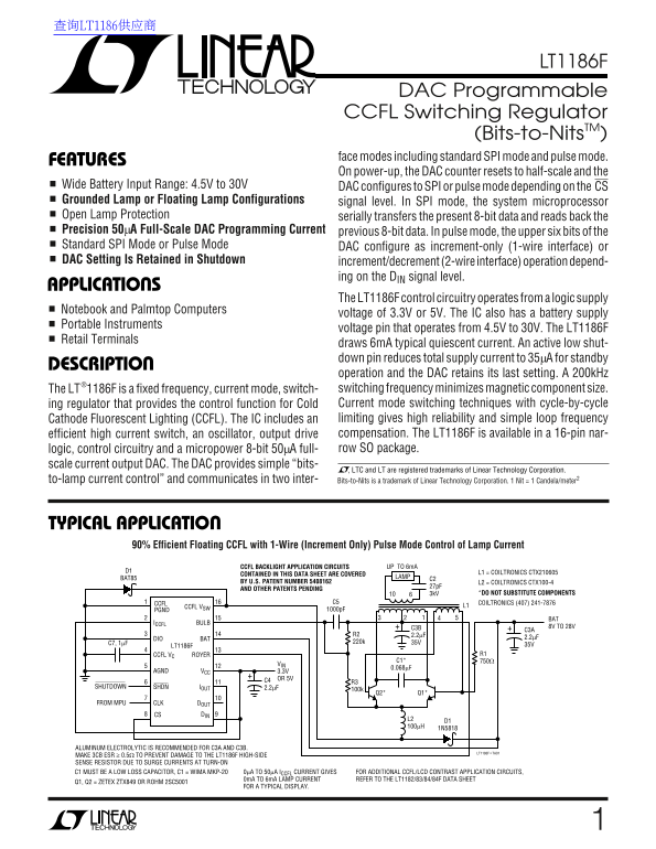
90% Efficient Floating CCFL with 1-Wire (Increment Only) Pulse Mode Control of Lamp Current
CCFL BACKLIGHT APPLICATION CIRCUITS UP TO 6m A
D1 L1 = COILTRONICS CTX210605
CONTAINED IN THIS DATA SHEET ARE COVERED
BAT85 LAMP
BY U.S. PATENT NUMBER 5408162 L2 = COILTRONICS CTX100-4
AND OTHER PATENTS PENDING
3k V *DO NOT SUBSTITUTE COMPONENTS
CCFL C5 COILTRONICS (407) 241-7876
CCFL VSW L1
PGND 1000p F
ICCFL BULB
C3B 8V TO 28V
DIO BAT 2.2µF
LT1186F 35V
CCFL VC ROYER R1
AGND VCC 3.3V
C4 OR 5V
SHUTDOWN SHDN IOUT 2.2µF
FROM MPU CLK DOUT
CS DIN
ALUMINUM ELECTROLYTIC IS RECOMMENDED FOR C3A AND C3B.
LT1186F • TA01
MAKE 3CB ESR ≥ 0.5Ω TO PREVENT DAMAGE TO THE LT1186F HIGH-SIDE SENSE RESISTOR DUE TO SURGE CURRENTS AT TURN-ON
C1 MUST BE A LOW LOSS CAPACITOR, C1 = WIMA MKP-20 0µA TO 50µA ICCFL CURRENT GIVES FOR ADDITIONAL CCFL/LCD CONTRAST APPLICATION CIRCUITS, 0m A TO 6m A LAMP CURRENT REFER TO THE LT1182/83/84/84F DATA SHEET
Q1, Q2 = ZETEX ZTX849 OR ROHM 2SC5001
FOR A TYPICAL DISPLAY.
Page Summary Contents For LINEAR TECHNOLOGY LT1186F Data Sheet
Manual Details
| Brand | Linear |
|---|---|
| Pages | 16 |
| File Size | 205.91 KB |
| Published | June 03, 2026 |
Enter the captcha to get the download link:

Frequently Asked Questions
What are the supported battery voltage ranges for this regulator?
The nWide Battery Input Range supports voltages from 4.5V up to 30V.
How can I reduce power consumption when the device is idle?
Using an active low shutdown pin reduces the total supply current to 35mA for standby operation.
What logic voltage supplies are available for the control circuitry?
The LT1186F's control circuitry operates from a logic supply of either 3.3V or 5V.
Which operational modes does the device support beyond standard SPI mode?
It supports both standard SPI mode and pulse mode, which depends on the CS signal level.