LINEAR TECHNOLOGY LT3014 Specifications and User Guide
Summary
The LT3014 is a micropower linear regulator engineered for demanding high-voltage and battery-powered systems requiring stable power at only 20mA output. Designed with extreme efficiency in mind, it features an ultra-low quiescent current (as low as 7µA) and operates across a wide input range (3V to 80V). This comprehensive manual provides details on technical specifications, mounting guidelines, package options, and application insights. It is essential reading for electrical engineers designing specialized electronics for mission-critical applications in telecom, automotive, or other high-voltage industrial environments needing reliable power efficiency.
Page 1 Text Content
LT3014
20m A, 3V to 80V
Low Dropout Micropower
Linear Regulator
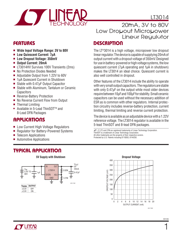
FEATURES DESCRIPTION n Wide Input Voltage Range: 3V to 80V The LT®3014 is a high voltage, micropower low dropout n Low Quiescent Current: 7µA linear regulator. The device is capable of supplying 20m A of n Low Dropout Voltage: 350m V output current with a dropout voltage of 350m V. Designed n Output Current: 20m A for use in battery-powered or high voltage systems, the low n LT3014HV Survives 100V Transients (2ms) quiescent current (7μA operating and 1μA in shutdown) n No Protection Diodes Needed makes the LT3014 an ideal choice. Quiescent current is n Adjustable Output from 1.22V to 60V also well controlled in dropout. n 1µA Quiescent Current in Shutdown
Other features of the LT3014 include the ability to operate
n Stable with 0.47µF Output Capacitor
with very small output capacitors. The regulators are stable
n Stable with Aluminum, Tantalum or Ceramic
with only 0.47μF on the output while most older devices
Capacitors
require between 10μF and 100μF for stability. Small ceramic
n Reverse-Battery Protection
capacitors can be used without the necessary addition of
n No Reverse Current Flow from Output
ESR as is common with other regulators. Internal protec-
n Thermal Limiting
DR OP OU VO LT AG (m V) tion circuitry includes reverse-battery protection, current
■ Available in 5-Lead Thin SOTTM and
limiting, thermal limiting and reverse current protection.
8-Lead DFN Packages
The device is available as an adjustable device with a 1.22V
APPLICATIONS reference voltage. The LT3014 regulator is available in the
5-lead Thin SOT and 8-lead DFN packages.
n Low Current High Voltage Regulators
L, LT, LTC and LTM are registered trademarks of Linear Technology Corporation.
n Regulator for Battery-Powered Systems
Thin SOT is a trademark of Linear Technology Corporation. n Telecom Applications All other trademarks are the property of their respective owners. Protected by U.S. Patents including 6118263, 6144250.
n Automotive Applications
TYPICAL APPLICATION
5V Supply with Shutdown Dropout Voltage
IN OUT 5V
VIN 20m A
LT3014 3.92M
5.4V TO
SHDN ADJ GND 1.27M
3014 TA01
VSHDN OUTPUT <0.3V OFF >2.0V ON
OUTPUT CURRENT (m A)
3014 TA02
3014fd
Page Summary Contents For LINEAR TECHNOLOGY LT3014 Specifications and User Guide
Manual Details
| Brand | Linear |
|---|---|
| Pages | 16 |
| File Size | 188.68 KB |
| Published | May 31, 2026 |
Enter the captcha to get the download link:

Frequently Asked Questions
What is the required output capacitor for stable operation?
The LT3014 is stable with only a small 0.47μF ceramic, tantalum, or aluminum capacitor on the output.
Does this regulator incorporate reverse-battery protection?
Yes, it includes thermal limiting, current limiting, and reverse-current protection circuitry.
What are the device's operational temperature limits in ThinSOT package?
The ThinSOT package operates from –65°C to 150°C.
Can this regulator handle transient voltage inputs?
The LT3014HV variant survives 100V transients over a 2ms period.