# A B C D E F G H I J K L M N O P Q R S T U V W X Y Z

LINEAR TECHNOLOGY LT3825 Specifications and User's Guide

Summary

The LT3825 is an advanced synchronous isolated switching regulator controller perfect for designing high-efficiency medium-power flyback supplies (10W to 60W). This modern controller eliminates the need for traditional optoisolators by sensing output voltage directly from the primary side. The manual details its functionality for applications including medical, telecom equipment, and Power over Ethernet, offering features like wide input range operation, synchronous driving, and precise output regulation without external trimmers. Ideal for engineers building reliable, isolated DC/DC converters.
📄 Preview PAGE OF 32

Page 1 Text Content

LT3825

Isolated No-Opto

Synchronous Flyback Controller with Wide Input Supply Range

FEATURES DESCRIPTIO

Senses Output Voltage Directly from Primary Side The LT®3825 is an isolated switching regulator controller Winding—No Optoisolator Required designed for medium power flyback topologies. A typical Synchronous Driver for High Efficiency application is 10W to 60W with input voltage limited only Input Voltage Limited Only by External by external power path components. A third transformer Power Components winding provides output voltage feedback.

Accurate Output Regulation Without User Trims

The LT3825 is a current mode controller that regulates

Switching Frequency from 50k Hz to 250k Hz

output voltage based on sensing secondary voltage via a

Synchronizable

transformer winding during flyback. This allows for tight

Load Compensation

output regulation without the use of an optoisolator,

Programmable Undervoltage Lockout

improving dynamic response and reliability. Synchronous

Available in a Thermally Enhanced 16-Lead

rectification increases converter efficiency and improves

TSSOP Package

output cross regulation in multiple output converters. APPLICATIO S The LT3825 operates in forced continuous conduction mode which improves cross regulation in multiple winding

Isolated Medium Power (10W to 60W) Supplies

applications. Switching frequency is user programmable

Isolated Telecom, Medical Converters

and can be externally synchronized. The part also has load

Instrumentation Power Supplies

compensation, undervoltage lockout and soft-start circuity.

Isolated Power over Ethernet Supplies

OU TP UT (V EF FI CI EN CY , LTC and LT are registered trademarks of Linear Technology Corporation.

All other trademarks are the property of their respective owners. Protected by U.S. Patents, including 6948466, 5841643.

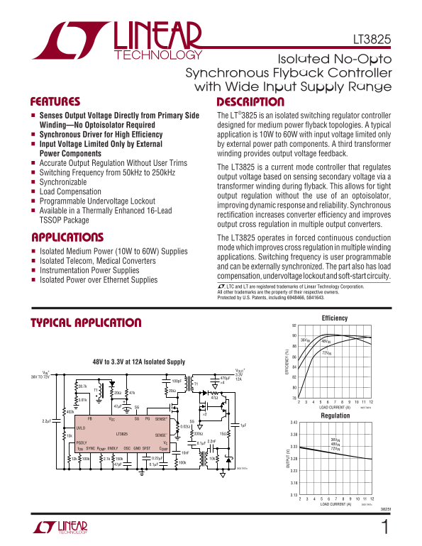
Efficiency

TYPICAL APPLICATIO

36VIN 48VIN

72VIN

48V to 3.3V at 12A Isolated Supply

36V TO 72V 470µF

47µF SG LOAD CURRENT (A) 3825 TA01b

Regulation

FB VCC SG PG SENSE+

2.2µF SG 3.43

LT3825 15Ω330Ω 3.38

15k SENSE–

36VIN

VC 2.2n F0.1µF

PGDLY 48VIN

t ON SYNC RCMP ENDLY OSC GND SFST CCMP 72VIN

3825 TA01a

LOAD CURRENT (A) 3825 TA01c

Page Summary Contents For LINEAR TECHNOLOGY LT3825 Specifications and User's Guide

Page 1 LT3825 Isolated No-Opto Synchronous Flyback Controller with Wide Input Supply Range FEATURES DESCRIPTIO Senses Output Voltage Directly from Primary Side The LT®3825 is an isolated switching regulator ...
Page 2 LT3825 ABSOLUTE AXI U RATI GS PACKAGE/ORDER I FOR ATIO (Note 1) VCC to GND TOP VIEW Low Impedance Source –0.3V to 18V SG PG Current Fed VCC PGDLY (VCC has Internal 19.5V Clamp) 30m A into VCC t ON RCM...
Page 3 LT3825 ELECTRICAL CHARACTERISTICS The ● denotes specifications which apply over the full operating temperature range, otherwise specifications are TA = 25°C. – = 0V; RCMP = 1k, Rt ON = 90k, RPGDLY = 2...
Page 4 (V SE NS VO LT AG (m V) (V LT3825 TYPICAL PERFOR A CE CHARACTERISTICS VCC(ON) and VCC(OFF) VCC Start-Up Current vs Temperature vs Temperature VCC Current vs Temperature VCC(ON) DYNAMIC CURRENT CPG = 1...
Page 5 SF ST HA RG CU RR EN (µ A) (V /V (µ A) LT3825 TYPICAL PERFOR A CE CHARACTERISTICS Feedback Amplifier Output Feedback Amplifier Source and Feedback Amplifier gm Current vs VFB Sink Current vs Temperatu...
Page 6 N( IN ) ( ns LT3825 TYPICAL PERFOR A CE CHARACTERISTICS Minimum PG On Time vs Temperature PG Delay Time vs Temperature Enable Delay Time vs Temperature Rt ON(MIN) = 158k RENDLY = 90k RPGDLY = 27.4k GD...
Page 7 LT3825 PI FU CTIO S VC (Pin 9): Pin used for frequency compensation for the sense resistor to reduce noise problems. SENSE– con- switcher control loop. It is the output of the feedback nects to the gr...
Page 8 LT3825 BLOCK DIAGRA VCC CLAMPS VCC UVLO 19.5V ERROR AMP 15.3V VC REFERENCE (VFB) 3V INTERNAL REGULATOR COLLAPSE DETECT UVLO SFST CURRENT OVERCURRENT IUVLO COMPARATOR FAULT SENSE– CURRENT SENSE AMP CUR...
Page 9 LT3825 FLYBACK FEEDBACK A PLIFIER T1VFLBK FLYBACK R1 LT3825 FEEDBACK AMP VFB VIN 1.25V ISOLATED PRIMARY SECONDARY COUT OUTPUT COLLAPSE DETECT MS ENABLE 3825 FFA UW TI I G DIAGRA VFLBK PRIMARY SIDE 0.8...
Page 10 LT3825 OPERATIO The LT3825 is a current mode switcher controller IC amplifier compares the voltage to the internal bandgap designed specifically for use in an isolated flyback topol- reference. The fe...
Page 11 LT3825 OPERATIO developed under these conditions, forced continuous enable time described to a maximum of roughly the “off” operation normally occurs. See Applications Information switch time minus th...
Page 12 LT3825 OPERATIO VFLBK T1 Average primary side current is expressed in terms of output current as follows: R1 FB Q2 VFBQ1 IN OUT R2 LOAD where COMP I MP OUT Eff IN RCMPF SENSE+ 50k So the effective cha...
Page 13 LT3825 APPLICATIO S I FOR ATIO Transformer Design For a multiple output transformer, the turns ratio between output windings is critical and affects the accuracy of the Transformer design/specificatio...
Page 14 LT3825 APPLICATIO S I FOR ATIO As a rough guide, leakage inductance of several percent (of Secondary Leakage Inductance mutual inductance) or less may require a snubber, but Leakage inductance on the ...
Page 15 LT3825 APPLICATIO S I FOR ATIO Ripple current and percentage ripple is largest at mini- The main design goals for core selection are reducing mum duty cycle; in other words, at the highest input coppe...
Page 16 LT3825 APPLICATIO S I FOR ATIO Setting Feedback Resistive Divider above nominal so IPK = 3.64A . If there is a 10% tolerance on RSENSE and minimum VSENSE = 80m V, then RSENSE • The expression for VOUT...
Page 17 LT3825 APPLICATIO S I FOR ATIO 4. Compute: SENSE 1• NCMP SF= 5. Verify this result by connecting a resistor of this value from the RCMP pin to ground. 6. Disconnect the ground short to CCMP and connec...
Page 18 LT3825 APPLICATIO S I FOR ATIO The t ON(MIN) resistor is set with the following equation: between the primary side switch and secondary side synchronous switch(es) and the subsequent current spike ns ...
Page 19 LT3825 APPLICATIO S I FOR ATIO The bias current on this pin depends on the pin voltage Even with good board layout, board noise may cause and UVLO state. The change provides the user with problems wit...
Page 20 LT3825 APPLICATIO S I FOR ATIO Switching action commences and the converter begins to operate the LT3825 directly from the available supply. In deliver power to the output. Initially the output voltag...
Page 21 LT3825 APPLICATIO S I FOR ATIO next cycle. This action naturally holds the VC voltage stable It is possible for the peak primary switch currents as during the current comparator sense action (current ...
Page 22 LT3825 APPLICATIO S I FOR ATIO Output Voltage Error Sources For the primary-side power MOSFET, the peak current is: The LT3825’s feedback sensing introduces additional IN MIN sources of errors. The fo...
Page 23 LT3825 APPLICATIO S I FOR ATIO For each secondary-side power MOSFET RMS current is where: given by: RDR is the gate driver resistance (≈10Ω) VTH is the MOSFET gate threshold voltage DCRMS MAX f OSC is...
Page 24 LT3825 APPLICATIO S I FOR ATIO Synchronous Gate Drive Keep input capacitor series resistance (ESR) and induc- tance (ESL) small, as they affect electromagnetic interfer- There are several different wa...
Page 25 LT3825 APPLICATIO S I FOR ATIO charging/discharging ∆V. This percentage ripple changes, The design of the filter is beyond the scope of this data depending on the requirements of the application. You ...
Page 26 LT3825 APPLICATIO S I FOR ATIO The total IC dissipation is computed as: immediately adjacent to the VCC and GND pins on the IC package. This capacitor carries high di/dt MOSFET gate PD(TOTAL) = VCC • ...
Page 27 LT3825 APPLICATIO S I FOR ATIO Place the small-signal components away from high fre- For applications with multiple switching power converters quency switching nodes. This allows the use of a pseudo- ...
Page 28 LT3825 EF FI CI EN CY TYPICAL APPLICATIO S 48V to 5V at 8A Isolated Supply VOUT 5V 470µF 8AVIN 6TPE470MI 0.1µF 36V TO 72V P6SMB100A MBRS1100 BAS21 47µF 0.1µF 402k 29.4k R7 1% 1% 20Ω Si7336ADP Si4490DY...
Page 29 LT3825 EF FI CI EN CY TYPICAL APPLICATIO S 48V to 3.3V at 6A Isolated Supply T1 PULSE PB2134 VOUT 3.3V 150µF 6AVIN 6TPB150ML 0.1µF 36V TO 72V BAS21 47µF 0.1µF Si4490DY FMMT618 Si7892DP FMMT718 VCC PG ...
Page 30 LT3825 EF FI CI EN CY TYPICAL APPLICATIO S 48V to 3.3V at 12A Isolated Supply L1 0.1µH VOUT 36V TO 72V T1 C1 TO C4 C5 12A 28.7k BAS21 250V Si4490DY 47µF SG Si7336ADP 2.2µF FB VCC SG PG SENSE+ 15k LT38...
Page 31 LT3825 PACKAGE DESCRIPTIO FE Package 16-Lead Plastic TSSOP (4.4mm) (Reference LTC DWG # 05-08-1663) Exposed Pad Variation BC SEE NOTE 4 2.94 (.252) (.116) 0.45 ±0.05 BSC 0.65 BSC 2RECOMMENDED SOLDER P...
Page 32 LT3825 RELATED PARTS PART NUMBER DESCRIPTION COMMENTS LT1424-5 Isolated Flyback Switching Regulator 5V Output Voltage, No Optoisolator Required LT1424-9 Isolated Flyback Switching Regulator 9V Output ...

Manual Details

Brand Linear
Pages 32
File Size 335.59 KB
Published June 19, 2026
5 views

Enter the captcha to get the download link:

captcha

Frequently Asked Questions

Does the LT3825 require an optoisolator for voltage sensing?

No, it uses synchronous transformer winding sensing, eliminating the need for an optoisolator.

What type of power applications is this controller best suited for?

It is ideal for isolated medium power supplies, typically ranging from 10W to 60W.

Can the switching frequency be adjusted or controlled by external signals?

Yes, the switching frequency is user programmable and can also be externally synchronized.

How does the device improve performance and reliability during operation?

It incorporates Programmable Undervoltage Lockout (UVLO) and soft-start circuitry to improve dynamic response.