# A B C D E F G H I J K L M N O P Q R S T U V W X Y Z

LINEAR TECHNOLOGY - LT1939 User Guide

Summary

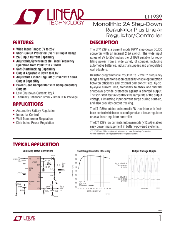
This versatile power management IC is a high-efficiency step-down DC/DC regulator seamlessly integrated with linear control features. Designed for robust performance across wide input voltage ranges (3V–25V), it provides critical protections, including soft-start and short-circuit coverage. Technical specifications detail its suitability for professional engineers developing complex power solutions in automotive, industrial, or distributed battery systems.
📄 Preview PAGE OF 24

Page 1 Text Content

LT1939

Monolithic 2A Step-Down Regulator Plus Linear Regulator/Controller

FEATURES DESCRIPTION n Wide Input Range: 3V to 25V

The LT®1939 is a current mode PWM step-down DC/DC

n Short-Circuit Protected Over Full Input Range

converter with an internal 2.3A switch. The wide input

n 2A Output Current Capability

range of 3V to 25V makes the LT1939 suitable for regu-

n Adjustable/Synchronizable Fixed Frequency

lating power from a wide variety of sources, including

Operation from 250k Hz to 2.2MHz automotive batteries, industrial supplies and unregulated n Soft-Start/Tracking Capability

wall adapters.

FF IC IE

n Output Adjustable Down to 0.8V

Resistor-programmable 250k Hz to 2.2MHz frequency

n Adjustable Linear Regulator/Driver with 13m A

range and synchronization capability enable optimization

Output Capability

between effi ciency and external component size. Cycle-

n Power Good Comparator with Complementary

by-cycle current limit, frequency foldback and thermal

Outputs

shutdown provide protection against a shorted output.

n Low Shutdown Current: 12μA

The soft-start feature controls the ramp rate of the output

n Thermally Enhanced 3mm × 3mm DFN Package

voltage, eliminating input current surge during start-up, and also provides output tracking.

APPLICATIONS

The LT1939 contains an internal NPN transistor with feed-

n Automotive Battery Regulation

back control which can be confi gured as a linear regulator

n Industrial Control

or as a linear regulator controller.

n Wall Transformer Regulation

n Distributed Power Regulation The LT1939’s low current shutdown mode (<12μA) enables

easy power management in battery-powered systems. L, LT, LTC and LTM are registered trademarks of Linear Technology Corporation. All other trademarks are the property of their respective owners.

TYPICAL APPLICATION Dual Step-Down Converters Output Voltage Ripple Switching Converter Effi ciency

BAT54

BSTVIN

6V TO 25V

LT1939

6.8μH VOUT1 VOUT1 = 5V AT 1A

SW 5V AC COUPLED

B240A 1A 2m V/DIV

SS 22μF

0.47μF FB

PG 8.06k

PG VOUT2 = 3.3V AT 1A AC COUPLED

2m V/DIV

RT/SYNC LDRV VIN = 12V

VC IOUT2 = 0A

FREQUENCY = 800k Hz

330p F 24.9k VOUT2

LFB 3.3V 1939 TA01c

0.4 0.6 0.8 1.0 1.2 1.6 1.8 2.01.40.2 500ns/DIV

40.2k 1A 8.06k 22μF LOAD CURRENT (A)

1939 TA01b

1939 TA01a

Page Summary Contents For LINEAR TECHNOLOGY - LT1939 User Guide

Page 1 LT1939 Monolithic 2A Step-Down Regulator Plus Linear Regulator/Controller FEATURES DESCRIPTION n Wide Input Range: 3V to 25V The LT®1939 is a current mode PWM step-down DC/DC n Short-Circuit Protected...
Page 2 LT1939 PIN CONFIGURATIONABSOLUTE MAXIMUM RATINGS (Note 1) TOP VIEW VIN, PG, PG Operating .................................... 25V/–0.3V VIN SW SW .........................................................
Page 3 LT1939 ELECTRICAL CHARACTERISTICS The l denotes the specifi cations which apply over the full operating temperature range, otherwise specifi cations are at TJ = 25°C. VVIN = 15V, VRT/SYNC = 2V, unless...
Page 4 LT1939 TYPICAL PERFORMANCE CHARACTERISTICS Shutdown Threshold and Minimum Feedback Voltage vs Temperature RT/SYNC Voltage vs Temperature Input Voltage vs Temperature 0.815 MINIMUM INPUT VOLTAGE 1.06 0...
Page 5 IM s) LT1939 TYPICAL PERFORMANCE CHARACTERISTICS Power Good Thresholds vs Power Good Sink Currents vs Temperature Temperature Frequency vs Temperature 0.75 RRT/SYNC = 90.9k RISING EDGE FALLING EDGE 0....
Page 6 LT1939 TYPICAL PERFORMANCE CHARACTERISTICS Minimum Boost Voltages vs Boost Current vs Switch Current Temperature Minimum Input Voltage 150°C VOUT1 = 5V VOUT1 = 3.3V 2.1 MINIMUM BOOST FOR SWITCH SATURA...
Page 7 LT1939 PIN FUNCTIONS PG (Pin 4): The power good pin is an open-collector PG (Pin 7): The power good bar pin is an open-collector output that sinks current when the FB or LFB falls below output that si...
Page 8 LT1939 BLOCK DIAGRAM IL IV IR IT FB –+ Fi gu re LT lo ck ia gr am
Page 9 LT1939 OPERATION The LT1939 is a constant frequency, current mode buck the VC pin is driven low disabling switching and the soft- converter with an internal 2.3A switch plus a linear regula- start lat...
Page 10 LT1939 OPERATION a drive voltage higher than VIN to saturate the output NPN A power good comparator with 30m V of hysteresis trips and maintain high effi ciency. when both FB and LFB are above 90% of ...
Page 11 LT1939 APPLICATIONS INFORMATION The following example along with the data in Table 1 where VSW is the voltage drop of the internal switch, illustrates the tradeoffs of switch frequency selection. and ...
Page 12 LT1939 APPLICATIONS INFORMATION Note that the LT1939 will regulate if the input voltage is a physically smaller inductor, or one with a lower DCR taken above the calculated maximum voltage as long as ...
Page 13 LT1939 FR k H z) APPLICATIONS INFORMATION Discontinuous operation occurs when IOUT is less than capacitor is required to reduce the resulting voltage IL/2 as calculated above. ripple at the LT1939 and...
Page 14 LT1939 APPLICATIONS INFORMATION surge currents when the input source is applied, tantalum are free to use ceramic capacitors to achieve very low capacitors should be surge rated. The manufacturer may ...
Page 15 LT1939 APPLICATIONS INFORMATION The ESRs of most aluminum electrolytics are too large to typical value of 3A, determined by the peak switch current deliver low output ripple. Tantalum and newer, lower...
Page 16 LT1939 APPLICATIONS INFORMATION Generally, for outputs of 3.3V and higher the standard cases the discharged output capacitor will present a load circuit (Figure 5a) is the best. For outputs between 2....
Page 17 LT1939 APPLICATIONS INFORMATION LT1939 CURRENT MODE SW POWER STAGE VOUT1 gm = 3mho R1 CPL CC CF TANTALUM ERROR AMP POLYMER CERAMIC RC gm = 250μmhos Figure 6. Model for Loop Response is much lower than...
Page 18 LT1939 APPLICATIONS INFORMATION the synchronization circuitry to the LT1939 as shown in the Typical Applications section. This will allow the LT1939 R2= VH 0.76 to start up with a switching frequency ...
Page 19 LT1939 APPLICATIONS INFORMATION When the SS pin voltage is below 100m V, the VC pin is The PG pin has a sink capability of 400μA when the FB and pulled low which disables switching. As the SS pin volt...
Page 20 LT1939 APPLICATIONS INFORMATION increases the overall effi ciency of the system. However, the minimum VIN increases to 2V plus the VGS at full load VOUT AC COUPLED of the transistor. Additionally, due...
Page 21 LT1939 APPLICATIONS INFORMATION VIN LT1939 LT1939 VIN LT1939 SW SW SWVIN GND GND GND Figure 11. Subtracting the Current when the Switch is On (11a) from the Current when the Switch is Off (11b) Reveal...
Page 22 LT1939 TYPICAL APPLICATIONS High Effi ciency Linear Regulator Effi ciency vs Load Current D2 BAT54 4.5V TO 25V BSTVIN 2.2μF LT1939 0.47μF 3.3μH SW SHDN R1 SS 25.5k 8.06k RT/SYNC LDRV R7 ZXMN2A03E6 VC ...
Page 23 LT1939 PACKAGE DESCRIPTION DD Package 12-Lead Plastic DFN (3mm × 3mm) (Reference LTC DWG # 05-08-1725 Rev A) PACKAGE OUTLINE 0.45 BSC 2.25 REF RECOMMENDED SOLDER PAD PITCH AND DIMENSIONS APPLY SOLDER ...
Page 24 LT1939 TYPICAL APPLICATION 1.8V/2A Step-Down Regulator VOUT2 4.5V TO 25V LDRVVIN 3.3V 2.2μF LT1939 SS BST 40.2k D1 VOUT1 RT/SYNC SW 1.8V VC FB R1 PG 10k PG 22μF R6 R2 49.9k 8.06k 1939 TA05 RELATED PAR...

Manual Details

Brand Linear
Pages 24
File Size 359.79 KB
Published June 16, 2026
1 views

Enter the captcha to get the download link:

captcha

Frequently Asked Questions

What is the minimum input voltage range for the LT1939?

The LT1939 operates from a wide input range of 3V to 25V.

Can the device be used with automotive batteries?

Yes, the LT1939 features an NPN internal transistor, allowing it for Automotive Battery Regulation applications.

How does power good monitoring help prevent issues?

The Power Good Comparator detects a shorted output and the outputs shutdown to provide protection against such events.

What is the adjustable output voltage capability?

The output can be resistor-programmable and adjusted down to 0.8V.